Correct Fastener Preload: What We’re Trying to Achieve
Before we dive into the comparison of bolt tensioning vs. torquing, let’s remind ourselves what we’re trying to achieve when we use either.
The ultimate goal in bolting is to achieve the correct fastener preload (also known as bolt load or axial load). Applied appropriately to a gasketed bolted connection, the bolt load creates clamping force (or “clamp load”) on the gasket. The result: A reliable, leak-free seal.
Bolt torque and bolt tensioning are both legitimate ways to seal a joint. Bolt torquing exerts a rotational force on the fastener, while bolt tensioning involves stretching a fastener with what looks like a hydraulic load cell.
Which is the “best method”?
Well, a torque wrench sales guy would tell you torquing is the way to go. A tensioner sales or service guy would tell you tensioning is the best way to do things. But really, which is “best” is a loaded question, and depends on…
Joint criticality
Joint component accessibility
Available equipment
Expertise of personnel
…and more.
In this article, we’ll provide definitions of for bolt torquing and bolt tensioning, explain some pro’s and con’s for each, and offer guidelines for the use of each.
NOTE: For the sake of everyone’s time, we’re not going to talk about tension indicators, hydraulic bolts, or direct tension indicating washers.
What is Bolt Torquing?
Torquing is the most commonly used way to achieve fastener preload with bolted joints. Torquing produces this load through rotational force on a nut or bolt head. This torque is usually measured in foot-pounds (ft-lbs.) or Newton-meters (Nm).
Whether the bolt torque is achieved through the use of a manual “clicker” torque wrench, pistol grip torque wrench, or a hydraulic torque wrench, it is the most simple method of achieving axial load.
The big advantage to torquing is that is typically more cost-effective than tensioning.
However, the skill levels and training of those who use the torque tools equipment are determinants of how successful and accurate torque tightening will be.
Additionally, to achieve correct torque-tension relationship, the K-factor is critical. (And note, K-factor is NOT the same thing as coefficient of friction.) A proper K-factor is critical for understanding what applied torque value you will need.
You also need to take into account friction on bearing surfaces, the bolt diameter, and other variables, which are best examined through experimentation.
What is Bolt Tensioning?
As mentioned above, bolt or stud tensioning produces axial load by pulling up on a fastener with what looks like a hydraulic load cell.
To achieve the targeted bolt load, you need to know the area of the tensioner and the amount of force on the fastener, and then adjust the amount of hydraulic pressure.
Hydraulic tensioning began in the 1970s, and in the 50+ years since, tensioning has become more common on specific applications, especially high-pressure flanges with large bolt diameters or critical joints across many industries, including oil and gas, wind, subsea, and power generation.
Because tensioning does not place a twisting force on the fastener as applied torque does, we see tensioners used with long threaded fasteners and on rotating equipment such as reciprocating rods.
Another good use of tensioning is large bolt diameters. On large bolt diameters, tensioning will save you time compared to using hydraulic torque wrenches.
Bolt Torquing vs. Tensioning: What’s More Accurate?
Tensioning is more precise — but there are ways torquing can narrow the gap, if it’s applied correctly.
Torque tools are generally considered accurate within plus or minus 30%. That means if your target was 50 KSI of load, you could see anywhere between 35 KSI and 65 KSI bolt load on your fasteners, and you’d be okay with that.
(The differences in bolt load from fastener-to fastener in flange is known as “bolt scatter.” The lower the bolt scatter, the more consistent the flange assembly.)
With tensioning, you’re typically going to see +/- 10% accuracy. That means your bolt scatter will be lower. If the target was 50 KSI, you’d see values between 45-55 KSI.
However, there are some important caveats to note here.
First, tensioning is more expensive and more complicated than torquing. So you will need people who have been properly trained in order to properly apply stud tensioning. Torquing, on the other hand, is fairly simple and torque wrenches are readily available in any industrial plant.
Second, torquing can be significantly more accurate than 30% when performed by an appropriately trained assembler, with proper lubrication and with calculations that include a proper (experimentally determined) K-factor. It’s not uncommon for well-trained craft assemblers to achieve +/- 15% accuracy or better with torquing.
Subscribe to Hex Technology today and we’ll give you $700 in bolting courses, FREE. Your path to a safer, more reliable, more profitable site starts here.
A 200,000 BPD U.S. refinery wanted to be a leader amongst its peers for mechanical integrity. The easiest, most impactful step? Improving bolted flange joint makeup. They partnered with Hex Technology to create a scalable solution for training hundreds of full-time craft and embedded contractors – and it’s already paying off.
“Now that our bolted joint program is up and running, we’re seeing much more consistent flange makeup.”
– Maintenance Supervisor
U.S. Refinery
QUICK HIGHLIGHTS
400+ assemblers trained in 4 months (130 staff, 270 contractors)
3-year program executed within 1 year
Winner of Corporate Excellence Award
HOW THINGS WERE
Hex master trainer Andy Smith demonstrates why impact drills are poor flange assembly tools.
The refinery prided itself on quality within its bolting processes and procedures. But a site visit and assessment by Hex Technology showed multiple opportunities for improvement.
Even though the refinery was a leader amongst peers under its corporate umbrella, site assessment scores revealed sound procedures hampered by a need for greater acumen among personnel.
This means assemblers and contractors interviewed during the assessment were less familiar with technical aspects bolted flange joints than they realized.
On topics like bolt elongation, gasket stress, or load control techniques, almost no assembler or contractor possessed sufficient knowledge.
The refinery relied heavily on QA/QC of bolted joints. But the problem with such measures is that they are reactive, not proactive. While QA/QC is an essential part of assembly, it is no replacement for having properly trained personnel.
To improve their site’s performance, the refinery again turned to Hex Technology.
“REDUCED LEAKS BY 99%”
Today the refinery’s bolting program accounts for every step and stakeholder in assembly – including staff and contractors.
“Now that our bolted joint program is up and running, we’re seeing much more consistent and reliable flange makeup. We’re not stressing joints,” the refinery Maintenance Supervisor says.
It starts with more knowledgeable and skilled crews. The refinery focused on training, using a hybrid model of computer-based training (CBTs) and hands-on work with programs developed by Hex Technology.
These trainings helped level the playing field among refinery staff and contactors and helped ensure everyone on-site is speaking the same language.
“[Today] Our site nested contractors have a higher level of craftsmanship and understanding of bolted joint make-up due to completing Hex CBTs, classroom training, and practical training,”
– Maintenance Supervisor
U.S. Refinery
Craft assemblers are putting that enhanced knowledge to work in the field. They better understand the “why” behind site procedures.
Crews are filling out the proper documents. And they’re doing a better job of inspecting and providing feedback on crucial elements like flange surfaces, allowing the site to take corrective action instead of putting a potentially risky element back in service.
Discrepancies are getting noticed, documented, and addressed – which means they’re being repaired. Even better, bolted joints are being assembled correctly resulting in reduced rework. The Supervisor says maintenance hours spent on rework have decreased since the program launched.
He adds that the site’s bolting program has reduced leaks on exchanger bundles by 99%.
THE HEX DIFFERENCE: In their words…
✅ “Safety.”
✅ “Reduced risk of process leaks.”
✅ “Enhanced mechanical integrity.”
✅ “Leak-free start-ups.”
✅ “Craft joint make-up is more consistent and meets a higher standard.”
FROM VISION TO ACTION
Hex Technology and the refinery shared the same goal: Operational excellence on every joint, assembled by every crew, every day. Hex helped the site achieve that goal by:
1. Identifying Opportunities and Providing Solutions.
Hex senior leadership first conducted a site visit, examining every step from written procedures to hands-on work in the field and interviewing 10+ staff members. Hex then identified areas for improvement and delivered a plan for executing on them.
2. Improving Craft Skills with On-Site Training.
Hex’s master trainer led on-site sessions for staff and contractors. These visits included “Train the Trainer” sessions that provided crew leaders with a structure for educating current and future craft.
3. Enhancing Craft Knowledge with Scalable (and Non-Boring) CBTs.
Even among experienced craft personnel, technical bolting knowledge can be a need. Hex’s solution provided computer-based lessons available anywhere, anytime, on any device.
Assemblers enjoyed and learned from the content (“I got more positive feedback from the craft than negative –in fact, I got no negative feedback from anybody,” the Supervisor says), and the material was all delivered on an intuitive, user-friendly platform. (“This system is so easy, a child could use it,” according to a contractor foreman.)
4. Creating Practical Materials Melding Industry Bests with Site Needs.
All Hex Technology training and materials are based on the guidelines in ASME PCC-1, the leading document governing bolted flange joint assembly. Hex helped the refinery develop both practical (hands-on) tests and assembler field manuals that met PCC-1 guidelines and addressed key requirements specific to its site.
5. Building a Sustainable Program for Continuous Improvement.
Hex Technology doesn’t settle for once-and-done. We provide the infrastructure for a successful and sustainable bolting program – one that a site’s own staff could execute. Armed with knowledge from “Train the Trainer” and supported by CBTs and site-specific practical assessments, the refinery now has a foundation for bolting excellence that will withstand any challenges, whether they be turnarounds, staff turnover, or contractor change.
*Note: Hex Technology works under NDA and is keeping this success story anonymous according to that agreement. However, the supervisor quoted in this story is willing to speak directly with interested parties to verify the details. Contact us if you’d like to learn more.
Watch What Happens When You Take a Bolt Past Yield
Let’s start with the big myth about steel bolts and yield strength.
What we often hear from people in the field is: “Well, if the bolt is broken, it’s been put into yield.”
That’s not actually true.
The video below shows you what happens when a bolt goes past its yield point.
Note how you can’t tell there’s a problem with the threaded fastener just by looking. It’s easy to tighten the bolt past the yield point and not know you are past permanent deformation.
And notice how even after the steel bolt has surpassed minimum tensile strength, a nut will still run up and down the threads just fine.
What is Bolt Yield?
A bolt’s yield point is where the stress placed on a fastener surpasses its ability to recover its elasticity.
Remember: Steel may seem firm, but it’s actually an elastic material. That means when you fasten a bolt, you are actually stretching the material.
The stress applied to a bolt is known as “tensile stress” or “preload.” In the graph below, you’ll see stress graphed on the y-axis, while the amount of stretch on the fastener is shown on the x-axis.
The preload added to the threaded fastener remains pretty linear — until you reach the yield point. This is known as the proof load or proof stress, and it’s the maximum load a fastener can take before it hits permanent deformation (also known as plastic deformation).
When a fastener reaches a point of plastic deformation, in simple terms, this means the fastener won’t go back to its original shape. (Technically, this means the bolt won’t go back to being within .02% of its original shape.)
If you were to continue applying load and stretching the fastener, the stress-strain curve takes a bad downward path:
If we keep stretching the fastener until we hit the ultimate tensile strength (also called maximum load). This is when a bolt starts “necking” and, eventually, breaks.
But long before the fastener breaks, since the curve past the yield point is not linear, we do not know the preload of the stud. Therefore can’t predict the clamping force the fastener is placing on the flange.
Once we understand this we can address the property classes of each common material found in the industrial industry.
NOTE: This article will concentrate on ASTM A193 & ASTM A320 type of fasteners. It does not address metric bolts, SAE J429 (medium carbon alloy steel bolts), or ASTM A449 (medium carbon steel bolts).
What is the yield strength of common fasteners?
Different materials in steel bolts, and the different stress areas of those bolts, play a crucial role in the strength requirements for their bolting applications.
The material differences are pretty self-explanatory. But the stress areas have to deal with how the steel bolt is quenched during manufacturing. Since there is more material in larger bolts, it is harder to quench them. Therefore their yield strength is effected.
Below is a chart of the yield strengths and ultimate tensile strengths for common ASTM-193 bolt grades found in petrochemical bolting applications.
Should You Re-use Bolts?
As we’ve shown you in this article, most people don’t really know when they’ve actually put a bolt into yield. So the logical question becomes: “When can we re-use studs?”
Well, ASME PCC-1 states that when using controlled bolting methods such as torque or tension, the use of new bolts up to 1-⅛ inch diameter is recommended.
What does that mean? If you’re going to use controlled bolt load techniques like clicker wrenches, hydraulic torque wrenches or even tensioning, you should probably replace the bolts if they’re 1-⅛ inch diameter and below, because the cost of refurbishing those bolts is higher than replacing them.
Meanwhile, the industry in general has been moving to replacing fasteners when controlled bolt load (torque or tensioning) is used to get clamping force on a flange.
Hex Technology has heard how replacing all studs is expensive. But again, note that the recommendation is for times when controlled bolting is being used.
Why? Because while your torque value and preload are almost the same for new and used bolts, there are many variables that the fastener will encounter during operation.
These are hard to quantify, therefore it is easier, safer and less costly to replace the fasteners than to do an engineered assessment to determine if they need to be replaced in most cases.
Subscribe to Hex Technology today and we’ll give you $700 in bolting courses, FREE. Your path to a safer, more reliable, more profitable site starts here.
Galling, or damage to fasteners that can inhibit their movement and effectiveness, is one of the most frustrating things that bolted flange joint assemblers will run into in the field.
You’ll typically find galling takes place in applications involving:
stainless steel fasteners
fasteners that do not have anti-seize compounds applied
fasteners without adequate corrosion resistance materials (such as Teflon or PTFE)
high-temperatures
fasteners that have contact areas that have been damaged or contain high points
Unfortunately, there are many misconceptions about why galling (or what some call “cold welding”) occurs. Thankfully, there are several things you can do to prevent galling.
By the end, you’ll understand the basics of galling and have learned alternatives to help you eliminate galling through proper practices.
What is Galling?
Let’s start with the technical definition. ASTM G40 says:
“…galling is form of surface damage arising between sliding solids distinguished by microscopic, usually localized, roughening and creation of protrusions, i.e. lumps, above the original surface.”
The basic idea behind galling is that the metal from one surface ends up becoming part of the other surface. Galling occurs frequently when two metal surfaces slide against each other and high contact pressure builds.
As shown in the image above, galling can occur on any of the metal surfaces involved in bolting, from the bolt itself, to the nut, to the flange face.
There are many theories about why galling occurs. Not all of them are true.
Here are a list of the most commonly cited culprits. We’ll identify which are true, which are false, and hopefully end some conspiracy theories along the way.
Lack of Proper Lubrication (Anti-seize)
Proper anti-seize compounds are the best way to prevent galling between mating surfaces. A typical anti-seize compound contains about 60-70% solids. At high temperatures (about 400 degrees F), the remaining oil burns off, leaving the solids to protect from galling.
Anti-seize should be applied through the entirety of the thread surfaces, so that when the nut is rotated to the flange, a bead of lubricant “squishes” out the bottom of the nut surface (as shown in the image below).
Properly applied bolt lubricant. Note how the light gray lube “squishes” out between the black bolt and nut.
Use of Spray Film Lubricant
We DO NOT recommend using this lubricant. It doesn’t give you a consistent K-factor, which will negatively affect your bolt preload, and it does not have enough solids to sufficiently prevent galling.
Nickel Anti-Seize vs. Molybdenum Disulfide Anti-Seize
Nickel is not a great lubricant for bolted flanged joints in petrochemical applications, because nickel is a metal. Remember: In applying pre-load to a fastener, an assembler is essentially grinding metal on metal. Adding in another metal (nickel) can actually worsen the situation.
What you really want is a mineral to act as a barrier between the contact and mating surfaces. Molybdenum Disulfide is a mineral and will help prevent galling better than a nickel anti-seize.
NOTE: With the friction and high temperatures seen during torque and operation, Nickel anti-seize creates nickel oxide, a very hard particle that will actually scar the material.
Stainless Steel Bolts and Stainless Steel Nuts
These are often the worst offenders for galling. Some believe this is due to their having a softer material and high alloy content. We don’t have great information showing stainless steel fasteners being more susceptible to galling, but we see it a lot in the field.
Corrosion Applications
These fasteners typically have an outer coating (like PTFE) on the outside of the initial protective oxide coating to provide corrosion resistance. However, if you read our PTFE article you will see that the nuts have been drilled to allow for a greater thread allowance between the nut and stud to accommodate the coatings.
NOTE: You should always lubricate PTFE coated studs because at preloads of 30,000 psi or more, the coating will tear off and you will lose your corrosion resistance. Applying anti-seize to the fastener will help protect the stud.
High-Speed Torque vs. Slow-Speed Torque
We have seen no correlation between high-speed or slow-speed torque and galling, so long as the fasteners have had the proper amount of anti-seize applied.
Fine Thread and Coarse Threads
There’s no good data that shows whether fine threads or coarse threads are more prone to galling. What we do often see, however, is that coarse threads are typically used in places where proper amounts of anti-seize are not used (such as structural steel applications).
How to Prevent Galling
The number one thing you can do to prevent galling is to properly apply the anti-seize to the thread surfaces where the anti-seize fills the entire fastener valleys.
Another way you can prevent galling is to tension (instead of torque) the studs. Then they won’t see the friction inherent in torque and will be less susceptible to galling.
What is “Fake” Galling?
“Fake” Galling happens more than most assemblers would like to admit.
Most of the time, galling occurs on large fasteners (two-inch studs or larger) that are attached to large flanges (plates that are 5 inches or thicker).
Why is that?
It’s due to elastic interaction. This is what happens when you drop the load on one fastener — the other fasteners actually see an increase in bolt load.
What happens next? Most of the time, you’ll put your wrench on the second stud — and find it doesn’t move. The immediate reaction is that the fastener has galled. That’s fake galling in action.
Here’s how to prevent fake galling:
In a circular pattern, loosen the fastener by 1/2 flat of a nut all the way around the flange.
In severe cases where galling has occurred before, continue with one more round of 1/2 flat of nut rotation, before you completely unload any fastener.
This will gradually unload the fasteners and reduce the chance of fake galling happening.
NOTE: You MUST do this in a circular manner, not in a star pattern. If you do it in a star pattern you will see that every other stud will have added stress to it, and this won’t work.
Lubricants That Don’t Work
As we discussed earlier, to avoid galling you’ll want to stay away from spray lubricants and nickel-based anti-seize. However, you must ensure that the anti-seize compound that you are using is safe for your application.
Remember: PTFE-coated studs (either Xylon(R) or Teflon(R)) are good for corrosion resistance, but they do not have a good K-factor. You should add anti-seize when assembling them, so long as doing so won’t contaminate the process.
Lubricants That Do Work
Hex Technology has seen that a good molybdenum disulfide lubricant is the best for petrochemical applications. We have had success using these in other industrial settings as well.
Subscribe to Hex Technology today and we’ll give you $700 in bolting courses, FREE. Your path to a safer, more reliable, more profitable site starts here.
For the past 40 years, when the oil and gas industry thought of bolt lubricant, it focused on disassembly — i.e. the breakout torque seen at the bolt head or at the nut of the fastener.
What went unexplored until recently was how lubricant affects the Nut Factor on a fastener, which then affects tightening torque, and therefore effects the bolt tension.
But that’s just the beginning.
Through years of research and first-hand experience, we have found that many lube manufacturers don’t know how their lube performs in the field. They often don’t understand the difference between friction coefficient and Nut Factor.
That’s a problem, because you reach the applied torque on your fastener through understanding your Nut Factor. If those numbers are off, then your final torque values will be incorrect no matter what your torque reading might be.
In this article, we’ll help you avoid those problems by explaining:
Any lubricant is designed to reduce friction and wear between two surfaces in contact. Bolt lubricant is a little more complicated than that.
In the past, bolt lubricant has been associated with disassembly, and therefore many in the oil and gas will refer to it as “anti-seize.” But bolt lubrication is also crucially important for assembling flanges properly.
Using proper bolt lubrication practices will allow assemblers to achieve the ideal torque with a low degree of bolt scatter (which we define as differences among torque levels on different bolts holding together the same flange).
Proper bolt lubrication means:
Consistent frictional properties: In order to determine your torque value, you have to understand, and solve for your K-factor. K-factor, which can also be called “nut factor,” is an experimental number. It is not adequate to use a friction coefficient or a friction factor calculation. In fact, PCC-1 just took out Appendix J which is the Friction Factor Calculation.
Adequately Lubricated Fasteners: There are very few situations in bolting together flange joints where you can over-lubricate a stud. You should always be able to see a bead of lube “squish” out the bottom of the nut. This means that you have put adequate lubricant on all surfaces that need it.
Lower Breakout Torques (no galling): Galling is a form of wear caused by adhesion between sliding surfaces. When a material galls, some of it is pulled with the contacting surface, especially if there’s large amount of force compressing on the surfaces together. Certain lubricants, such as nickel lubricants, can actually cause galling.
Physical and chemical stability: In the past, the petrochemical industry used copper-based lubes in the past as their standard. However, they discovered these types of lubes don’t play well with hydrogen and can lead to hydrogen embrittlement, which can corrode, crack, or otherwise deteriorate surfaces. Then the industry moved to nickel-based lube, but there was another problem: It causes galling to accelerate. Now the industry has moved to moly lube. Moly lube is technically a mineral, helps prevent galling, and is good for most environments.
Ease of application: The ability to apply lubrication is a different subject than adequate lubrication. Why? If the lube can’t come out of the can because it’s a solid at lower temperatures, an assembler won’t be able to apply it adequately.
A Brief History of Thread Lubricant
As we mentioned earlier, bolt lubricants were initially thought of as anti-seize. Companies like Jet-Lube have produced anti-seize thread lubricants for 70+ years for the upstream industry. To this day, the use of copper-based lubricant Kopr-Kote(TM) is the standard lubrication in the field.
Therefore it doesn’t seem unreasonable that when the rest of the petrochemical and power industry started to focus on anti-seize products for a bolted joint, they turned to those copper-based lubricants. But they discovered copper lube was not good for all systems because it doesn’t play well with hydrogen.
Instead, the industry then turned to nickel-based lubricants. This type of lube was considered good because of its high-temperature rating, up to 2500 degrees Fahrenheit. (But note: That is the melting point of nickel and not a good method for determining what a good lube looks like.)
Recently the petrochemical industry has moved to molybdenum disulfide, which is also called “moly” lube. Currently this is the best type of lube for assembling bolted joints, because it does not cause hydrogen embrittlement if mixed with the correct chemicals.
(Note: Pure moly lubricants are not recommended around hydrogen. Check with the manufacturer.)
Why Use Bolt Lubricant?
There are two main reasons why lubricated fasteners are better than non-lubricated fasteners.
1. Galling
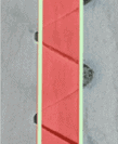
The top thread shows the effect of galling. (Image courtesy of MachineDesign.com)
Galling is one of the most frustrating things we run into in the field as assemblers.
The true definition of galling comes from ASTM G40, and it says galling is form of surface damage arising between sliding solids distinguished by microscopic, usually localized roughening and creation of protrusions, i.e. lumps, above the original surface.
So what does that mean to the assembler?
It means we’re grinding steel on steel to stretch steel. That’s what we’re doing when we use torque. So if we want to get rid of galling, one of the best ways to is to properly lubricate.
The other part of preventing galling is in what type of lubricant you are using. That’s why you’ve seen an increase of molybdenum disulfide lubricants (a.k.a “moly” lubricants) in the industry.
2. Achieving Proper Bolt Torque: An Introduction to K-Factor
Here we need to discuss:
Non-Lubricated Bolts (a.k.a. Dry Torque)
Partially Lubricated Bolts
Properly Lubricated Bolts
But before we talk about these items, or get to our torque chart, it is imperative you understand the working definition of K-Factor (or “Nut Factor”). ASME PCC-1 states:
“K is an experimentally determined, dimensionless constant related to the coefficient of friction.”
Translation: You need to have experimental data on what Nut Factor you have. DO NOT rely on just the coefficient of friction numbers. Some manufacturers will say they are the same, or they will not have done Nut Factor testing at all. PLEASE do your homework on this.
“Published tables of experimental nut factors are available from a number of sources; however, care must be taken to ensure that the factors are applicable to the application being considered.”
Translation: You need to make sure any previous testing was done on applications that represent what you are working with. For example, we once saw a company do a test on 1/4 inch bolts. The problem: The average size bolt in the petrochemcial industry is 3/4 inch. So those tests weren’t especially helpful.
“It should also be noted that recent research has shown there to be nut factor dependence on bolt material, bolt diameter, and assembly temperature. These factors can be significant and should not be ignored when selecting the nut factor or anti-seize compound. The user is advised either to seek test results conducted on similar bolt and anti-seize specifications or to conduct nut factortrials (size and material) with their own conditions.”
Translation: Get your hands on their research! It’s the only way you can verify that they have done their homework.
It’s not possible to determine an accurate Nut Factor for dry threads. Unfortunately, when you don’t have lubricant, there are many other substances that may act as lubes on your fastener that you might not be able to see.
One of them is the oil used on them during manufacturing. For example, we have seen a stud where the oil has been “baked off” using an oven have a Nut Factor of about .26, while a stud that still has oil residue is about a .20. (It’s worth noting that particles of solids still on the stud that will also affect your Nut Factor).
That is a big discrepancy.
Hex Technology recommends that you do not try to solve this problem unless you have the proper equipment and understand the “Turn of the Nut Method.”
Partially Lubricated Bolt Nut Factor:
Let’s say you’ve done your homework and understand the nut factor for your lube. If that lubricant isn’t applied generously/properly, the dry parts of the fastener will increase your Nut Factor and result in different bolt loads on each of your fasteners.
So you might be using a calibrated torque wrench, and have a known Nut Factor, but if your lube isn’t applied properly, your torque value (bolt tension) will have changed.
When testing your Nut Factor, you put it in the best and most repeatable condition, then you replicate those conditions in the field. By properly lubricating fasteners, you achieve the correct ft-lbs, clamping force/preload, and gasket stress.
How Much Lubricant Should You Use?
Proper lubrication means that you’ve put lubricant on every thread so that the valley of the stud is full.
Notice how we lubricate enough so that when you hand rotate the nut down, there’s a little bead of lube that squishes out. This means that we’ve put lubricant on all the parts that will experience friction when we apply torque.
How to Apply Bolt Lubricant
When you apply lubricant, be certain that all valleys of the stud bolt threads are filled.
Once the nut is hand tightened, you should see a bead of lubricant extruding from beneath the nut. This indicates that the lubrication has been applied to all working surfaces.
In this screenshot from the video above, notice how the varying levels of bolt lubrication lead to better results:
No lubrication: You will see that, without lubricant, bolt stress is lower than our target bolt stress of 40 Ksi. In the video above, our test on unlubricated studs test averages 28.8 Ksi, with the low amount being 27.3 and a high of 31.
Partial lubrication: Inconsistent or only partially lubricating the studs will result in unfavorable bolt stress. In the second test, by using lubricant the average bolt stress increased by 5.4 Ksi, but still came up short of our target of 40 Ksi. Bolts that are not lubricated in the same fashion will have a greater variation in the bolt load.
Proper lubrication: Properly lubricated studs will result in a tight bolt load at our desired stress target. Notice how bolt load has increased, and we’re now achieving bolt loads much closer to the target bolt load of 40 Ksi. And notice how the variation among the bolt loads (a.k.a. bolt scatter) has drastically reduced when all working surfaces are properly lubricated.
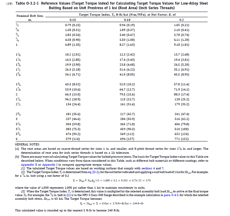
Bolt Lubricant Torque Chart
PCC-1 published Table O-3.2-1 “Reference Values (Target Torque Index) for Calculating Target Torque Values for Low-Alloy Bolting Based on Unit Prestress of 1 ksi (root area) (Inch Series Threads).
This was done to ensure you can use it to determine and adjust to stainless steel fasteners that have a lower tensile strength.
NOTE: The above chart shows you how to determine your torque IF you have either a 0.15, 0.18, OR 0.2 Nut Factor. But again you need to experiment with what lube you have and confirm the Nut Factor is in order to make a torque specification.
Subscribe to Hex Technology today and we’ll give you $700 in bolting courses, FREE. Your path to a safer, more reliable, more profitable site starts here.
PTFE is short for Polytetrafluoroethylene, a chemical applied to common bolting materials (such as B7 stud bolts) to provide corrosion and chemical resistance.
Some other common coatings for PTFE coated fasteners are Teflon® and Xylan®. In this article, we’ll refer to all of them as PTFE.
PTFE coated studs have been used for many years within the bolting industry, especially in any application that requires corrosion resistance or in offshore applications (salt spray is hard on Grade B7 material). PTFE is also useful if you’ve had “galling” and need a lower breakout torque for safe removal.
PTFE should not be used in high-temperature applications. Fluoropolymer coatings manufacturers use temperatures in the 400F-500F as the maximum temperatures, so you typically do not see alloy steel bolts (such as B8) with PTFE coatings.
While PTFE coated studs (including Xylan® coated studs) have corrosion-resistant properties, which are functionally understood by assemblers, the technical aspects of fluoropolymer coatings are often misunderstood.
For example, as an assembler, I was told that the PTFE coaching acted as a lubricant, which meant I didn’t have to mess with lubricating them after I put them into a flange.
It sounds like the perfect solution. The only problem is: That advice was wrong.
Way wrong, in fact.
Yet many front-line assemblers today still think it’s correct.
Thankfully, in the decades since I first started putting together flanges, smart minds both in the lab and on the front lines have given us a much more accurate picture of how PTFE coated studs work.
In this article we’ll bust some myths, provide practical advice, and address some of the most common questions we hear from craft assemblers today, including:
Click any of those questions above to jump directly to the answer you want. Or read on to get the complete picture of how PTFE coated studs affect assembly.
1. Are all PTFE coated studs the same?
Absolutely not.
While PTFE is the same as Teflon® on a chemical level, they are not applied the same way by each manufacturer. There also are several different types of base coats.
Therefore, the thickness of the coating on the fastener is not a standard — and quite frankly, it’s not controlled.
As a result, you must choose one manufacturer and test your k-factor for their product, and recognize that those values do not transfer to other PTFE coated stud manufacturers.
2. Do I lubricate PTFE coated Studs?
Yes!
At 30,000psi bolt load (not to be confused with 30% tensile strength), you start stripping your coating. Also, the coating will start binding. Therefore, you’ll have better accuracy and less bolt scatter (or differences in bolt loads on each bolt) by using lubricating them.
However, you will have to test your lubricant and manufacturer combination in order to correctly determine your K-Factor. Note: Don’t confuse K-Factor with low coefficient of friction, which is not used for this calculation.
(Learn proper lubrication techniques in our Level 1 course — now available free.)
3. Can I re-use PTFE coated studs?
You shouldn’t.
If you were to re-use PTFE coated studs, the corrosion-resistant coating on the threads will most likely be at least somewhat degraded or damaged, meaning your K-Factor will change again.
Physically the bolt might still hold up to corrosion. So visually, they would still look good, which would lead someone to think that the life expectancy of the stud would be longer. But appearances can be deceiving, and you shouldn’t reuse PTFE coated studs.
4. Why do PTFE studs have low friction and lower break out torque than regular studs?
What would you say if I told you that, in order to fit the nut on the stud with the PTFE coating, you must drill a bigger threaded hole (tap) through a 2H nut? Yes, it’s true. And there is are no technical specifications on this.
I couldn’t believe it either, but you will be effectively taking 30%-50% of the contact surface away. Therefore, it is not the PTFE that makes it easier to disassemble (and you have a low friction between stud and nut on assembly). This phenomenon is due to having considerably less contact area!
5. Does the PTFE coating help with corrosion resistance?
Yes…to an extent.
Let’s say you have a B7 stud (ASTM A193) and 2H nuts. The application process and proprietary materials of the PTFE coating is intended to help with corrosion resistance. However, since the coating is proprietary to the manufacturer, it is hard to say how well it helps with corrosion resistance.
One way to test this is with a salt spray test with ASTM B117, which sprays the stud bolts up to 3,000 hrs while not freezing the nuts.
A Brief History of PTFE
Before PTFE coated bolts came along, the petrochemical industry used other methods of making corrosion-resistant bolting components, such as hot dip, galvanized, cadmium or zinc-plated fasteners.
Polytetrafluoroethylene (PTFE) is a synthetic fluoropolymer of tetrafluoroethylene that has numerous applications. The most well-known brand name of PTFE-based formulas is Teflon by Chemours. Chemours, a spin-off from DuPont, originally discovered the compound in 1938.
PTFE (polytetrafluoroethylene) coatings are considered non-stick coatings. Therefore you need a process to apply the “non-stick” coating to the “B7 stud material”. Therefore, the typical manufacturing process is a three-step process.
Apply a corrosion resistant base coating
Apply an adhesion coating
Apply a polytetrafluoroethylene nonstick topcoat
It’s unclear exactly when the bolting industry started using PTFE coated studs, but they have been around for a while. They tend to be used in highly corrosive environments.
Once the bolts prove themselves, people start placing them all around the plant — regardless of whether or not they should or need to.
Bottom Line: I am not very fond of using PTFE coated studs as it increases the complexity of a bolted joint, you don’t have a consistent K-Factor (not “low coefficient of friction”). Unfortunately, PTFE coated studs are over-prescribed since most people don’t know how they actually work.
A Real-World Test of PTFE
When we started researching PTFE studs, we took standard B7s, B7s coated with PTFE, and a set of B7 Doxsteel studs. We then put them in the worst part of a plant: In the way of drift from a cooling tower. (If you notice in the photo at left, you’ll see an icicle hanging above the test flanges.)
Here’s what happened:
(From left: B7s coated with Doxsteel, B7s coated with PTFE, and standard B7s.)
So, out of the three pictures above, which would you say has the easiest break-out torque (some call it a low kinetic friction coefficient)?
My thoughts were: Doxsteel, PTFE, and then B7 studs.
Nope.
The B7 studs with PTFE were easier to break loose. I asked the CEO of Doxsteel about the testing, and why his studs were second best, and this is what he showed me.
Oversizing Nuts to Make PTFE Studs and Nuts Fit
One of the biggest issues in bolting is K-Factor, as it deals with how the friction when applying torque and proper lubricant will help with safe removal of the studs during disassembly.
We’ve found through testing that at about 30,000 psi of bolt load, you start to tear that PTFE coating off the stud and heavy hex bolts. (Learn more about high psi applications in our free course on Powered Equipment.) The coating ends up binding on the bottom of the nut and threads. This changes the binding of the PTFE, makes the K-factor change, and your bolt scatter is more dispersed.
Why does this happen? Well, it works together with a lower break out torque. The nuts are over-tapped!
Yup, as you can see in the picture on the top above, you will see normal engagement of a B7 stud. Then the picture on the bottom shows how PTFE manufacturers over tap the nut so that the coating can fit.
You can normally see 20%-40% less engagement of the threads. So it is not the PTFE that makes it easier to break loose, but actually the lack of engagement!
Other References to Review
It’s hard to find material on this topic that wasn’t published by a manufacturer. But here are a couple of interesting resources:
Doxsteel. These guys are responsible for the pictures above and testing with Hex.
Here’s a video I found on the application of PTFE. I can’t confirm, but I think that this is how all manufacturers apply it (which seems less technical than I ever thought).
Subscribe to Hex Technology today and we’ll give you $700 in bolting courses, FREE. Your path to a safer, more reliable, more profitable site starts here.
Not all bolt tightening sequences are created equal.
Bolted flange joint assemblers have been using the Star Pattern since Taylor Forge started standardizing on flanges in 1938.
The sequence has been used for pipe flanges on both ASME B16.5 and ASME B16.47 flanges (NPS 26 inch and above), heat exchangers, and other applications like butterfly valves.
You’ll see the Star Pattern applied to all types of gasket materials and flange types, including Raised Face (RF), Ring Type Joint (RTJ), Double-Jacketed, Spiral Wound Gaskets, and even newer gasket types like the Kammprofile gasket.
While the Star Pattern is the most common, it is certainly not the only — or necessarily the best — bolting pattern to apply when torquing a bolted flange assembly.
In fact, there is no “silver bullet” bolt tightening sequence ideal for torquing every type of flange or gasket. The gasket type, and arrangement of the flange connection, are both critical to choosing which tightening sequence an assembler can use.
This article, which is intended for supervisors, engineers, or anyone else who oversees bolted flange assembly or maintenance, will discuss different torque sequences. Along the way, we’ll offer guidance about which methods are best for achieving desired final torque values with minimum bolt scatter, and ensuring your gasket isn’t damaged in the process.
To keep the scope of this article reasonable, we won’t address other important elements of bolt tightening procedures like flange alignment, gasket installation, torque values, torque tables, how bolt torque needs to change for different materials (like stainless steel bolts), and so on. Those topics are covered in depth in lessons included our free online training.
What bolt tightening sequences are covered in ASME PCC-1?
ASME PCC-1 is probably the world’s leading guideline covering the assembly of bolted flange joints.
In the publication’s 2010 edition, ASME PCC-1 published an entire appendix (Appendix F) dedicated to bolt tightening sequences, including the Star Pattern (which it labeled the “Legacy Pattern” because the technique has been around so long) and several other options, which were classified as “Alternative” bolting patterns.
These alternative bolting sequences were included to demonstrate more efficient ways to assemble flange connections. Like the star pattern, the alternative approaches could be used with just about any tightening method from hydraulic torque to pneumatic torque to manual torquing with a clicker wrench.
Legacy (a.k.a. “Star”) Bolting Pattern
As we mentioned earlier, this is the most common of all bolt tightening sequences used on flanged connections. The pattern is well understood around the globe, and its use has stood the test of time.
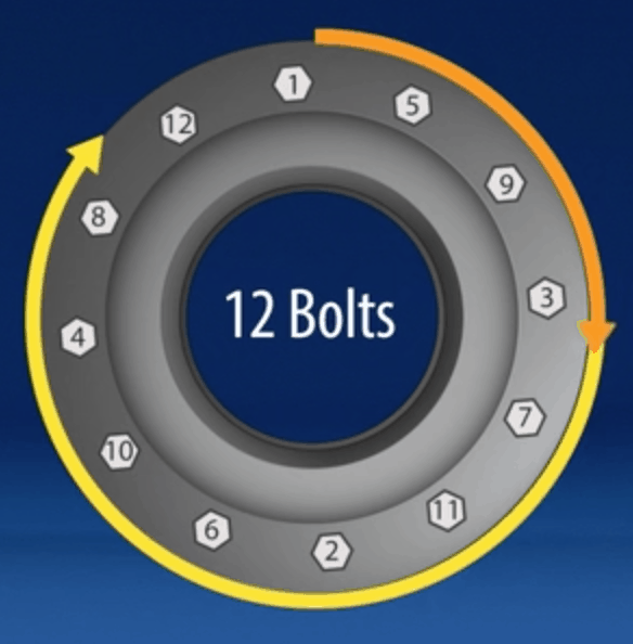
How to Perform the Star Pattern
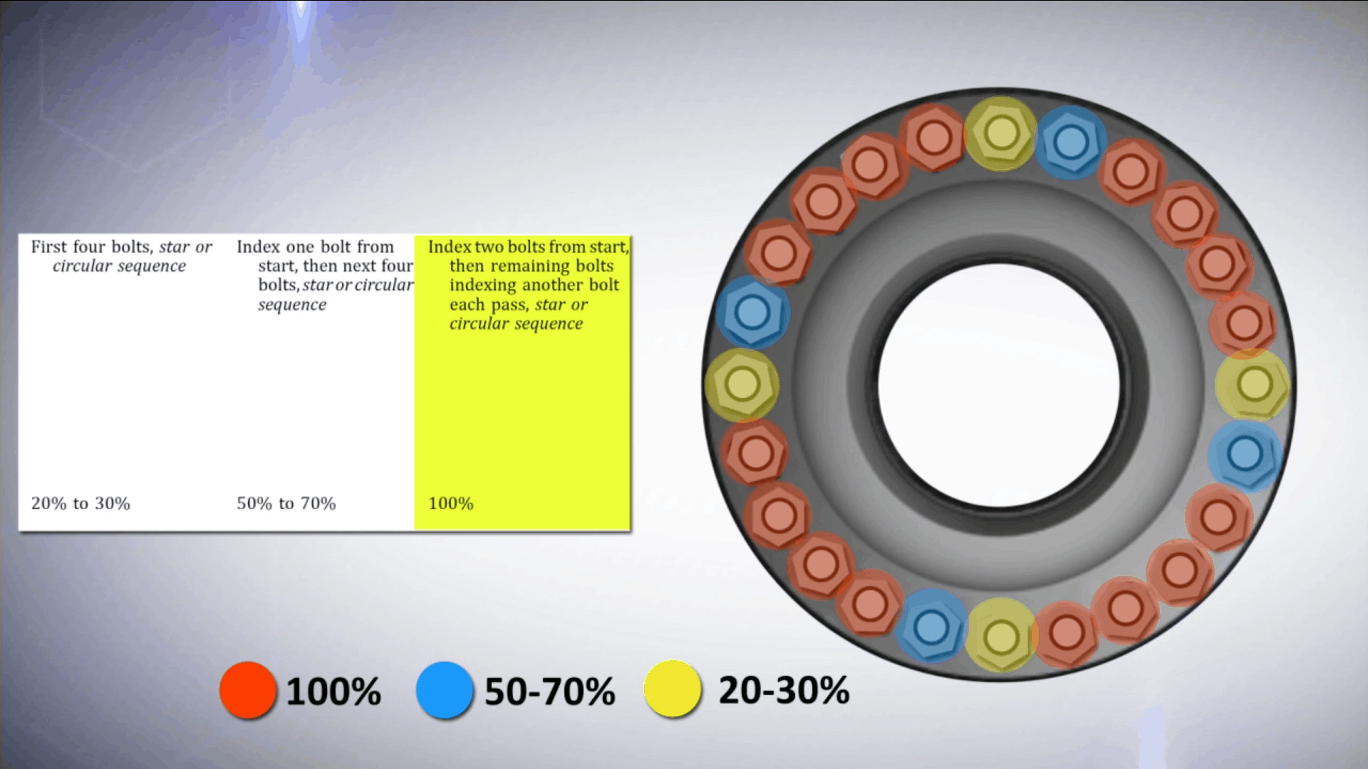
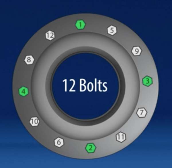
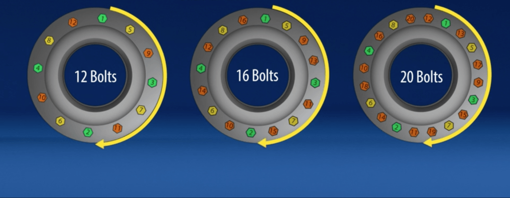
The first thing you do is tighten each flange bolt between 20% and 30% of your target ft-lbs in the star pattern. The pattern itself is to apply to bolts #1-4 below (in order):
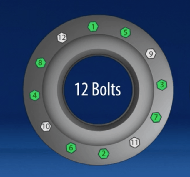
…then move to bolts 5-8, again, applying torque in order:
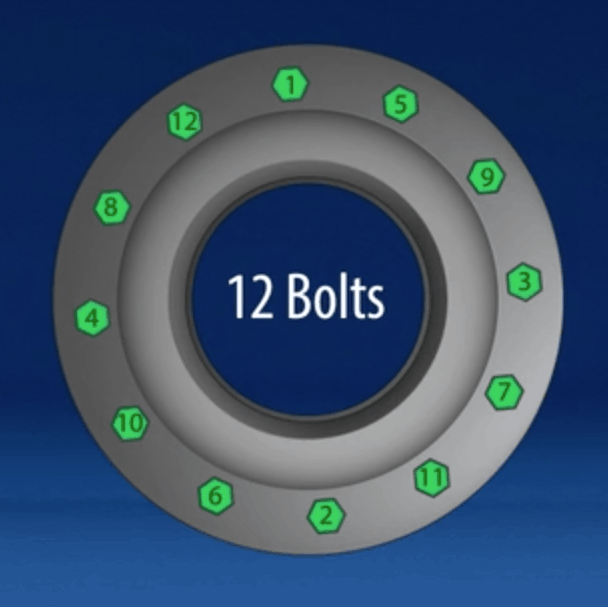
…and to complete this first step, you apply to bolts 9-12:
Now you have approximately 20-30% on all 12 bolts in this example flange. There will be variations due to elastic interaction, but that’s about the average.
Step #2 is to follow the same star pattern while applying 50% to 70% of the target ft-lbs.
Then the third part of this tightening sequence is to set your wrench at 100% of required torque (ft-lbs) and apply to all bolts while again following the same star pattern.
The final step is to apply rotational or “circular” passes.
You’ll typically go around the flange twice with the wrench set on your final torque value, but the goal is to go until the nuts stop moving.
Normally, with spiral wound gaskets or Kammprofile gaskets, this takes about two circular passes, but with RTJ gaskets you’ll need to perform additional ringer passes.
Restrictions: None. The star bolting pattern is good for use on all ASME B16.5, B16.47, and heat exchanger flanges. It’s also valid on all flange face and gasket types, including RTJ gaskets.
Recommendations: The drawback to the Star pattern is time. This bolting pattern is not as efficient as the alternatives, and can be very time consuming when you are working on flanges with 20 or more bolts. But if most of the flanges on your site are ASME B16.5 flanges sized 12” or smaller, you might want to stick with the Star Pattern and not implement other bolting patterns to avoid confusion with the assemblers.
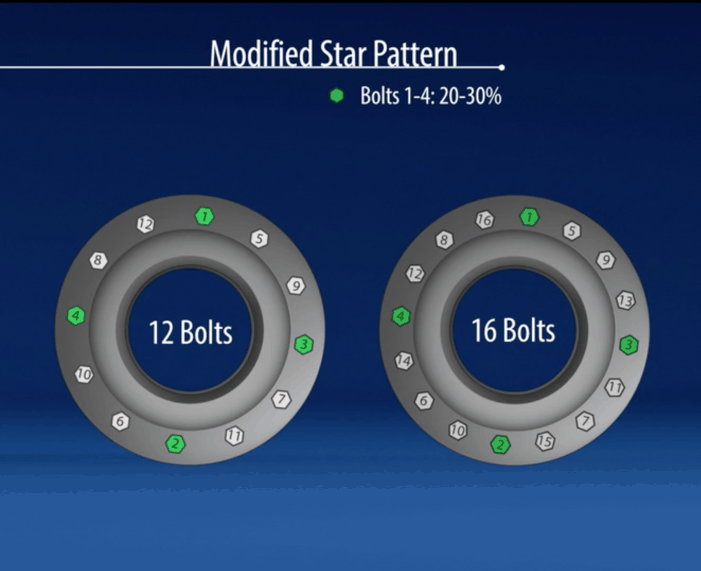
Modified Star Bolting Pattern
PCC-1 refers to the Modified Star as “Alternative Assembly Pattern #1,” and this bolt tightening sequence follows the same tightening pattern as the Star. What’s different is how preload levels on the fasteners preload increase more rapidly with this approach.
If you look at the diagrams below, you will see you how the assembler tightens flange bolts in the same order, but increases bolt load after just the first four bolts.
In fact, you can break down that first pass into three parts:
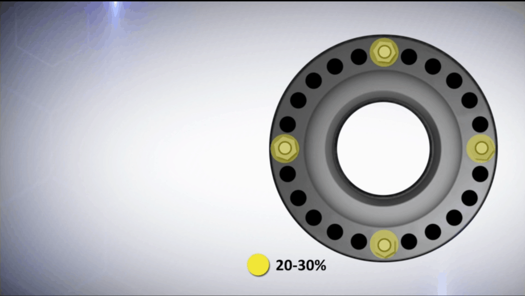
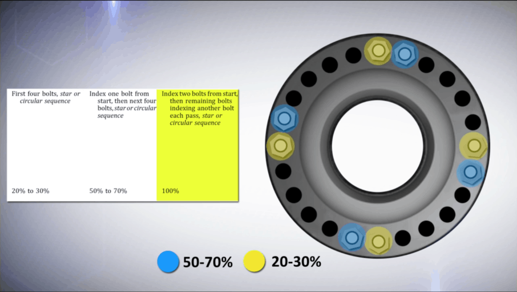
Pass 1A – Tighten the first four stud bolts to between 20% and 30% of your target ft-lbs.
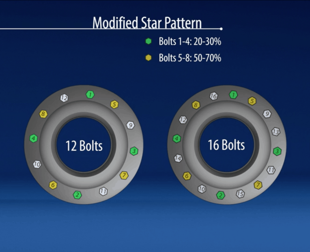
Pass 1B – Tighten the next four bolts in the Star Pattern to between 50% and 70% of the target ft-lbs.
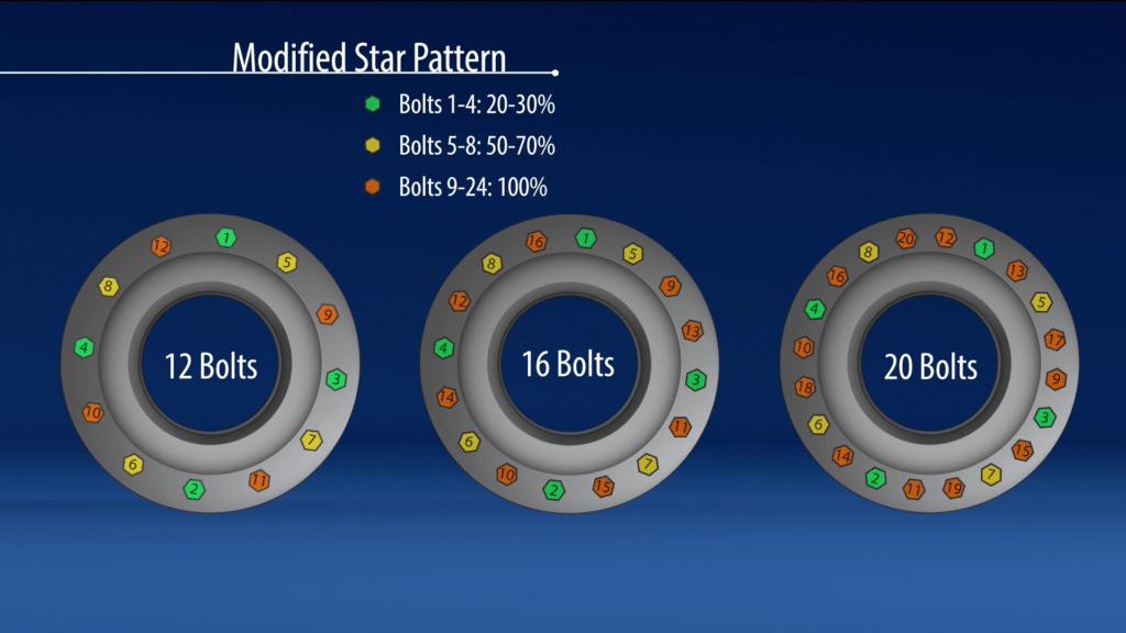
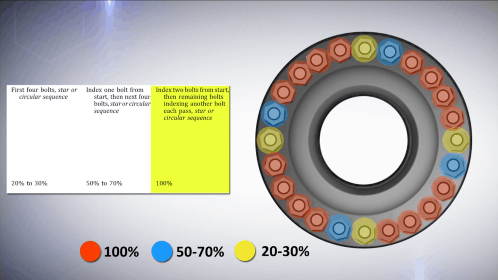
Pass 1C – Tighten the rest of the bolts in a star Pattern to 100% of your final torque.
Pass 2 – ASME PCC-1 states that soft gaskets (see ASME PCC-1 Appendix B for definitions on hard gaskets and soft gaskets) such as spiral wound and double jacketed gaskets must have a full star pattern completed. However, Kammprofile gaskets do not need Pass 2.
Pass 3+ – The final series of passes are rotational passes, where you go around the flange in a circle with your wrench set at the final torque value. Once again, you’ll go until the nuts stop moving. Normally, with spiral wound gaskets and Kammprofile gaskets, we see that this takes about two circular passes. RTJ gaskets require additional final passes.
The modified star’s approach means you’re able to perform fewer total tightening sequences, which in turn means less time and effort required since there are fewer total bolt touches overall.
Restrictions: None. Like the Star Pattern, the Modified Star is good for all ASME B16.5, B16.47, and heat exchanger flanges, and will cover all flange face and gasket types.
Recommendations: The Modified Star bolting pattern is much more time-efficient than the Star Pattern, especially when you are working on flanges with 20 or more bolts. The Modified Star can be helpful on some 16-bolt flanges, especially if they involve larger-sized studs (1-inch diameter or greater). You won’t be saving a significant amount of time with the Modified Star on flanges with 12 bolts or less.
There is a learning curve for the Modified Star bolting pattern, but it’s fairly easy for most assemblers to overcome since the only change is the gradual step up in torque values during your first pass.
Quadrant Pattern
The Quadrant Pattern, or “Alternative Assembly Pattern #3,” is more efficient than both the Star Pattern and Modified Star Pattern. With the Quadrant Pattern, fastener preload levels increase rapidly within the first tightening sequence.
You also don’t have to “criss-cross” the flange as much, which saves even more time. An added bonus is that experienced assemblers won’t need to number the flange when they are applying this pattern — so long as they were trained well.
The diagram below shows how the torque wrench moves only one bolt over after you have made your first “star sequence.”
You’ll also increase your bolt load settings after tightening your first four bolts. The diagrams below show how you will…
Pass 1A – Tighten the first four stud bolts to between 20% and 30% of your target ft-lbs.
Pass 1B – Tighten the next four bolts, placing each to the right of the already tightened bolts, to between 50% and 70% of the target ft-lbs.
Pass 1C – Tighten the rest of the bolts in the pattern to 100% of your final torque. You’ll continue applying torque on the bolt immediately to the right of the previously tightened bolt, following the pattern while working all the way around the flange.
Pass 2 – For any gasket other than a Kammprofile, you’ll need to repeat this pattern a second time. Kammprofile gaskets do not need Pass 2.
Pass 3+ – The final passes are rotational (i.e., “circular” or “ringer”) passes, where you set the wrench to your final torque value and go around the flange until the nuts stop moving. Normally, with spiral wound gaskets and Kammprofile gaskets, we see that this takes about two circular passes, but RTJ gaskets will need additional final passes.
Restrictions: None. This bolting pattern is good for all ASME B16.5 & B16.47, and heat exchanger flanges. It will also cover all flange face and gasket types including RTJ gaskets.
Recommendations: This bolting pattern is much more time-efficient than the Star & Modified Star Pattern when you have flanges with 20 or more bolts. The learning curve for this bolting pattern is fairly low, however, if your craft personnel aren’t assembling many flanges, you might want to stick with the Modified Star sequence.
Circular Pattern
While PCC-1 covers the use of the Circular Pattern, Hex Technology does not recommend the bolting pattern for the average assembler. The Circular Pattern can only be used with hard gaskets such as Kammprofile gaskets, and can not be used on spiral wounds, RTJs, or double-jacketed gaskets.
For that reason, we’ll leave the how-to for this pattern out of this article. If the pattern is in use at your site, you need assistance with it or wish to know more, please contact our service line at [email protected].
Subscribe to Hex Technology today and we’ll give you $700 in bolting courses, FREE. Your path to a safer, more reliable, more profitable site starts here.
However, in most joint designs, people attain clamp load by using a certain specified torque value with a torque wrench to generate bolt tension on the fastener.
What’s the problem with that?
Well, most of the time, that torque value requires adjustment. It needs to be adapted to the real-world conditions surrounding the application of the bolt.
This is where k-factor comes into play.
What is K-Factor in Bolt Torque?
K-Factor is a value that’s important for calculating the target input torque for your fastener.
An accurate k-factor can be determined only by doing experiments with the lubricant and fastener you plan to use.
Are K-Factor and Nut Factor the Same Thing?
Yes. The terms “k-factor” and “nut factor” are interchangeable.
However, k-factor (a.k.a. nut factor) is not the same as coefficient of friction or friction factor. Those are different methods for calculating torque value, which we’ll discuss later in this article.
Why is K-Factor Important?
You need to have an accurate k-factor in order to achieve a good torque-tension relationship when calculating the applied torque for threaded fasteners.
Applying the right amount of torque is essential for creating a good seal around the gasket, which keeps the stuff in the pipes inside the pipes.
Mating surfaces and bolt thread conditions can vary widely due to factors such as:
relatively loose nut and bolt thread manufacturing tolerances for threaded fasteners,
fastener thread condition issues that affect thread friction,
thread pitch,
new versus reused fasteners,
the presence of hardened washers versus nut rotation on the bearing surface,
variations in nut dimensions (see this article on PTFE for examples),
temperature,
and the presence of coatings and lubricants.
How To Determine K-Factor
There is a lot of confusion about how to calculate a k-factor.
There is currently no good ISO or ASTM standard for testing on fasteners. But there are several different ways you can test a k-factor.
The one we typically see involves…
Predicting what the installation torque should be on a fastener
Placing it on a load cell (measuring bolt elongation is acceptable but more labor-intensive)
Lubricating adequately (including bolt threads and mating surfaces) to reduce thread friction and friction on the bearing surfaces.
(This helps reduce the standard deviation among the results)
Applying torque with a calibrated torque wrench
Measuring what the clamping force on the flange would be by measuring the preload of the fastener
Once you determine your k-factor, you can plug it into the equation:
T = K D F/12
Where:
T = Target Input Torque (ft-lb)
This is your input torque from your torque wrench determined by your specified torque.
K = nut factor
This is your X if you are doing testing,
D = nominal diameter (bolt diameter) of the fastener (in.)
F = target preload (lb)
NOTE: do not confuse this with bolt yield point or yield strength that you are targeting, it is in pounds of force.
How Is K-Factor Different for PTFE Coated Bolts?
K-factor testing is essential for PTFE bolts.
Why?
Because there is no manufacturing standard in the industry for the coating applied to these fasteners. As a result, you have to test every manufacturer’s methods.
The k-factor for PTFE bolts is typically lower, since the nut has been over tapped to accommodate the coating.
The below k-factor chart is not for general use on bolted joints without understanding the variables you may have at your site, and the materials that you are using.
This chart is from ASME PCC-1 (2019) and is a “Target Torque Index.” It shows how your torque value will change with different k-factor values at 1-ksi (root area) bolt load.
The purpose of this Target Torque Index is only for examples on how to calculate your k-factor. It is NOT something you should blindly use.
Other Terms and Values to Know for Torque Value
Coefficient of Friction
In basic terms, the coefficient of friction is measured experimentally. It describes the ratio of the force of friction between two bodies and the force pressing them together, typically by using a decline plane with a block on it.
The drawback is that this method does not look at bolt preload for a bolted joint. it only addresses the coefficient of friction between a block and a decline plane. It’s not representative of what happens to a nut and a bolt during fastening.
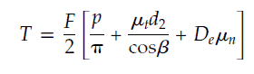
Friction Factor
Most friction factors are extremely complex. Certain aspects need to be determined experimentally. That is why we recommend the nut factor method.
But just doing math won’t help you out with this. You need to do some good ol’ testing.
There are several friction factor calculators used in the bolting industry. One that was recently taken out of ASME PCC-1 for the 2019 revision (previously in the 2013 version) was written as:
De = effective bearing diameter of the nut face, mm (in.) = (do + di)/2d2 = basic pitch diameter of the thread, mm (in.)
di = inner bearing diameter of the nut face, mm(in.)do = outer bearing diameter of the nut face, mm(in.)
F = bolt preload, N (lb)n = number of threads per inch, in.−1 (applies to inch threads)
p = thread pitch, mm (For inch threads, this is normally quoted as threads per inch)
T = total tightening torque, N·mm (in.-lb)
β = half included angle for the threads, deg
µn = coefficient of friction for the nut face or bolt head
Subscribe to Hex Technology today and we’ll give you $700 in bolting courses, FREE. Your path to a safer, more reliable, more profitable site starts here.
A gasket is meant to form a mechanical seal that fills the space between two or more mating surfaces. Its goal is to prevent leakage from, or into, the joined objects while under compression.
Gaskets allow for less-than-perfect mating surfaces on machine parts. They can fill irregularities and increase the likelihood of sealability — especially in high-pressure applications and flanges that have a high differential temperature range (cyclic flanges).
There are many different types of gaskets used in the oil and gas (petrochemical) industry and other heavy industry. They include both standard ANSI/ASME pipe flanges (an example is ASME B16.5 flanges) and gaskets used in heat exchangers.
What Nachos Can Teach You About Proper Gasket Assembly
What most people don’t know is that the gasket stress is what we care about the most! Not the bolt load.
We use this analogy when training people: “What is the purpose of the chip in chips and queso? It’s the vehicle that gets the queso to the mouth.”
That is the purpose of the bolt: To be the vehicle to gets the gasket stress correct.
What are the Most Common Types of Gaskets Used in Oil and Gas?
Here are the 8 types of gaskets you will see the most often:
1. Envelope Gasket (Double Jacketed Gaskets)
Envelope Gaskets can be either double jacketed gaskets, or they can have PTFE (some call it Teflon but that is a trademarked name) on the outside of a stainless steel metal core. However, they don’t have a lot of compression or recovery, and do not hold up to radial sheer (slipping of the flanges on the gasket during high-temperature fluctuations).
2. Flat Metal Gaskets
Source: Shutterstock
These gaskets usually have a stainless steel core without any filler material, and are used in low criticality applications. They also don’t have a lot of compressibility or recovery.
3. Non-Asbestos Sheet Material Gaskets
Non-asbestos sheet material is typically found with full-face flanges and have elastomeric properties, although they can be just graphite gaskets in few cases. One can have high chemical resistance sheet gaskets such as a PTFE/ePTFE gasket that has great compressibility and a little bit of recovery if you don’t overstress them.
Normally, these gaskets are used with low pressure and low temperature, but they can be also put in put in flanges where chemical resistance is needed. Most gasket manufacturers stock a wide range of elastomeric, non-elastomeric, PTFE/ePTFE, graphite gaskets, and compressed sheet material in both sheets and rolls.
4. Ring Type Joint
Source: Shutterstock.
Ring Type Joint gaskets are also called RTJ gasket, ring gasket or ring joint gaskets. They come in oval or octagonal shapes, which can be used in API 6A applications.
RTJ gaskets were traditionally found in high pressure and high-temperature applications, as sheet material elastomers can not hold up in those types of applications. But today RTJ gaskets are being phased out of high pressure and high-temperature applications, as spiral wound gaskets with inner rings are now the preferred gasket.
However, if you are using ring type joint gaskets, know that they are typically made of a soft stainless steel gasket material, and should be replaced after every use due to the plastic deformation that it sees in the flange. If you don’t replace it, you are jeopardizing the sealability of the gasket.
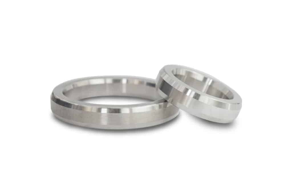
5. Kammprofile Gasket
Courtesy of Salmarcon.
You’ll also see Kammprofile spelled “camprofile gasket,” and they are sometimes called grooved metal gaskets. These types of gaskets are commonly found in heat exchangers in the oil and gas industry.
They are much more reliable than jacketed gaskets (double jacketed gaskets). Kammprofile gaskets are typically made of a stainless steel metal core with a flexible graphite filler material.
The area (a.k.a cross-section) of the gasket can be easily changed to achieve good gasket stress while withstanding a high bolt load. Kammprofile gaskets are also really great for radial sheer which is seen when the flanges slip on each other (really the flexible graphite filler) during flange expansion and contraction (due to temperature).
This gasket material is a solid metal gasket, and the metal core can be made of stainless steel or other exotic materials so that it can be put in high pressure and high-temperature flanges.
To learn more about Kammprofile Gaskets, click here.
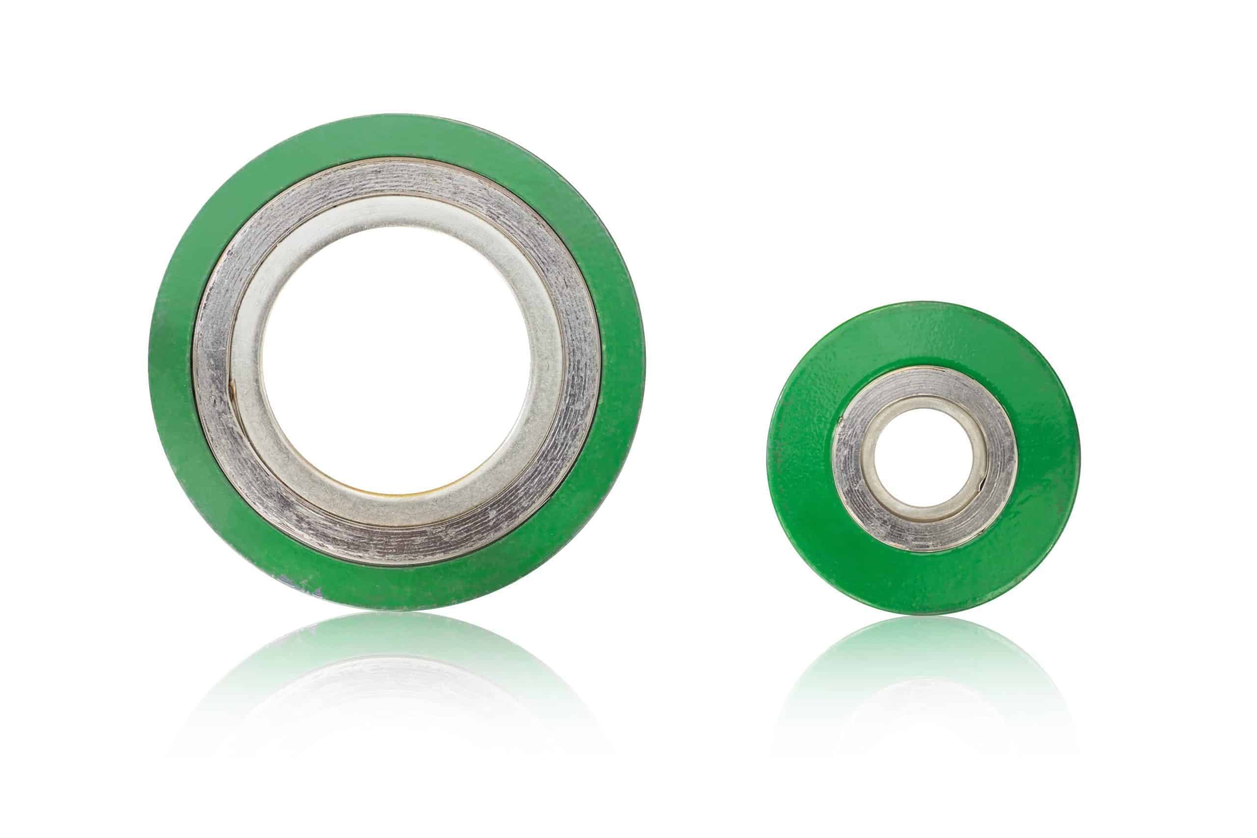
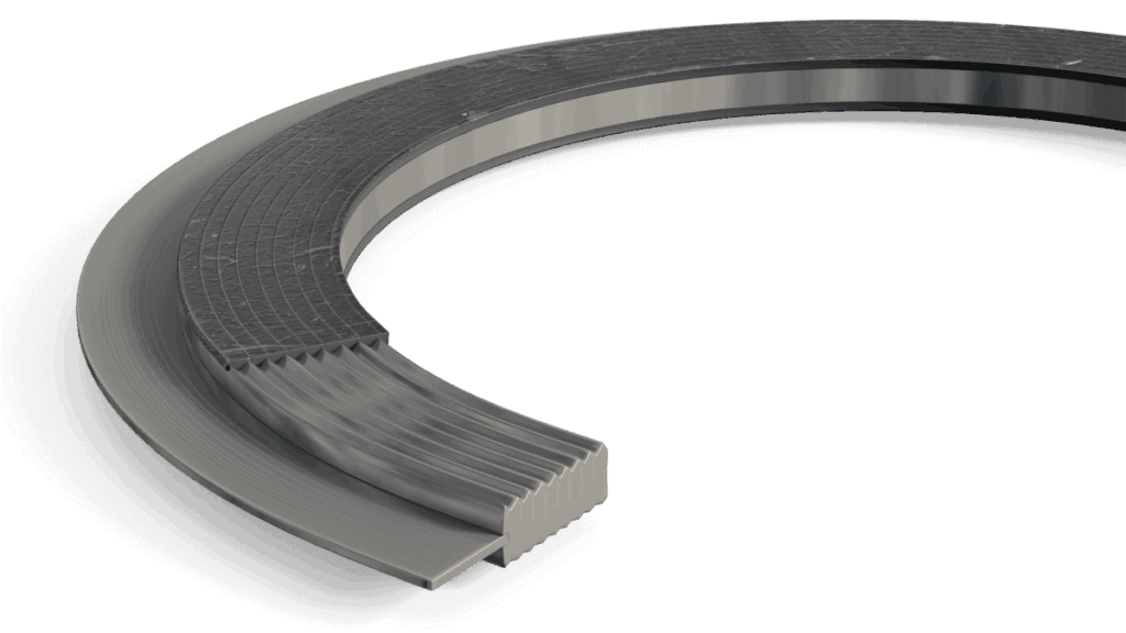
6. Spiral Wound Gaskets WITH an Inner Ring
Source: Shutterstock
These types of gaskets are the best metal gaskets for all pressure ratings of pipe flanges, especially ASME B16.5 flanges.
I would argue that they are also great for heat exchangers due to their sealability tolerances with imperfections in flanges, and because they can be made for high pressure and high-temperature applications.
These spiral wound gaskets have a stainless steel inner ring, a carbon steel outer ring, and the metal core is made of stainless steel windings. The filler material is typically flexible graphite, but you can also have an elastomeric filler material such as PTFE if chemical resistance is needed.
Spiral wound gaskets are more also flexible than Kammprofile gaskets so they tend to also have more compressibility and recovery, but they are harder to place in a flange at larger diameters so it is advisable to move to Kammprofile gaskets.
To learn more about Spiral Wound Gaskets, click here.
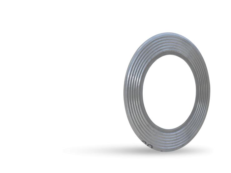
7. Spiral Wound Gaskets WITHOUT an Inner Ring
These types of gaskets should not be used in typical pipe flanges, and especially not in high-pressure rated pipe flanges (such as 600 pounds or greater).
The reason: Spiral wound gaskets without inner rings can buckle under high gasket stress, such as what you’ll see when there is a lot of bolt area and little gasket area.
There are instances when a spiral wound gasket without a stainless steel inner ring or carbon steel outer ring can be used for groove flanges such as male/female flanges, but we will typically see that they will compress enough to not allow for recovery.
8. Corrugated Metal Gaskets
Courtesy of Garlock.
These gasket types can be made to have a minimum of 0.5″ cross-section and have been used to change gasket area. They are better than metal jacketed gaskets for heat exchangers, but should not be used in standard piping flange gaskets.
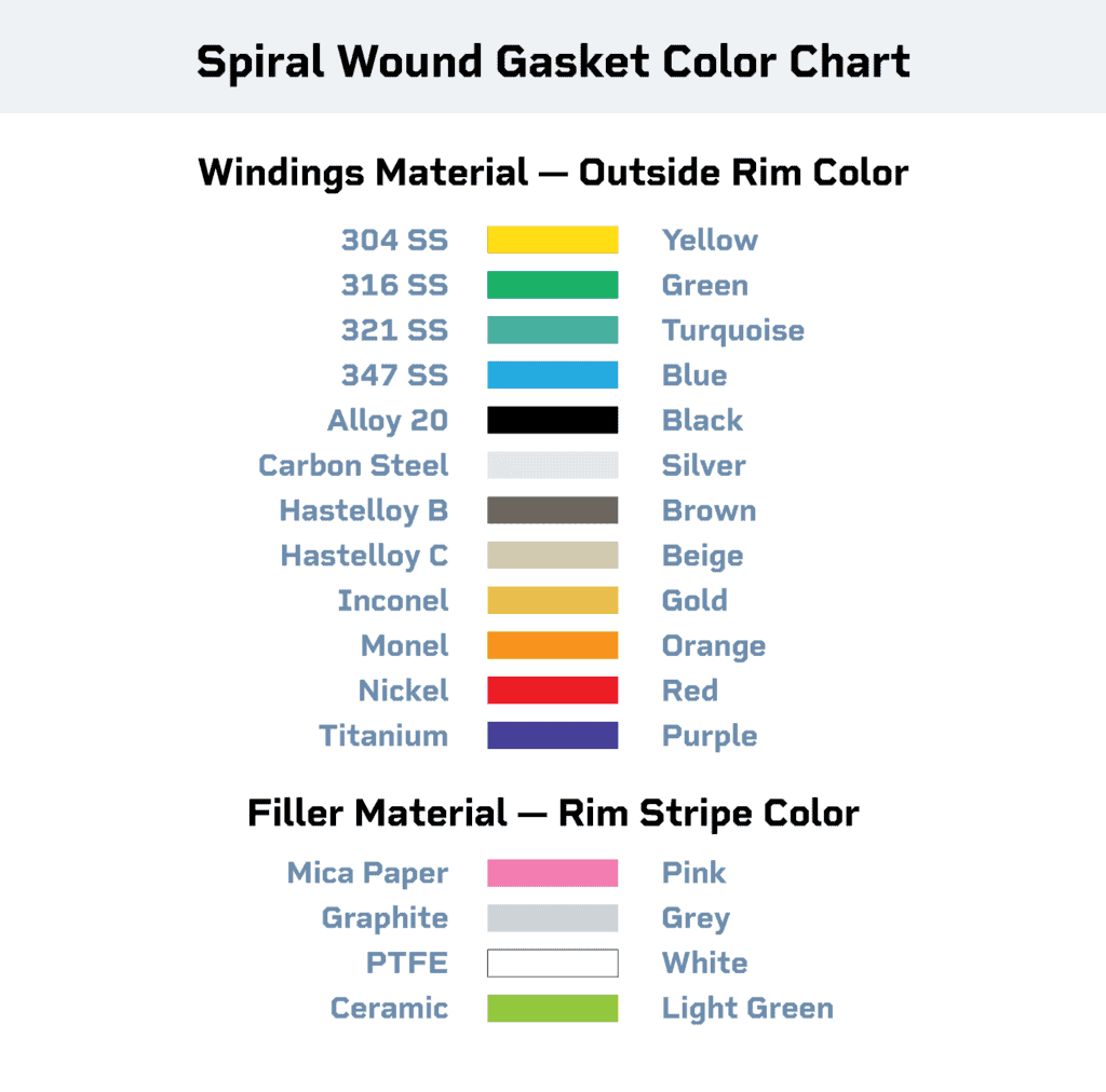
How to Identify a Gasket: A Color-Coded Chart
Most piping flange gaskets in the oil and gas industry today are spiral wound gaskets made of stainless steel for the metal core material with either PTFE or graphite filler material. ASME B16.20 offers a Color Coding Chart that is part of the standard for inspection purposes.
The color coating on the outer ring (which is typically carbon steel) is painted on the outside of the ring so that an inspector can identify the windings material.
Typically 316 stainless steel is used as the standard in petrochemical applications, as it is better for high-temperature applications. While 304 stainless steel could be used, most End Users in the petrochemical industry err on the conservative side for the 316 stainless steel which has a green color on the carbon steel outer ring.
The most common filler material is flexible graphite, and that is indicated by the grey stripe on the green outer ring.
The ASME B16.20 color chart above indicates what the gaskets are made of. NOTE: there is no marking for gaskets that do not have a stainless steel inner ring, so it is prudent that ALL spiral wound gaskets have an inner ring.
Subscribe to Hex Technology today and we’ll give you $700 in bolting courses, FREE. Your path to a safer, more reliable, more profitable site starts here.
ASME is short for the American Society of Mechanical Engineers. PCC-1 stands for “Post Construction Committee 1”. PCC-1 addresses “Guidelines for Pressure Boundary Bolted Flange Joint Assembly.”
It’s a consensus document, which means it was written by several experts across the bolting industry.
The document addresses many factors involved in bolting principles and the assembly of bolted flange joints. The scope of ASME PCC-1 states:
These guidelines for bolted flange joint assemblies apply principally to pressure-boundary flanged joints with ring-type gaskets that are entirely within the circle enclosed by the bolt holes and with no contact outside this circle.
These guidelines may be selectively applied to other joint geometries. By selection of those features suitable to the specific service or need, these guidelines may be used to develop effective joint assembly procedures for the broad range of sizes and service conditions normally encountered in industry.
This document uses the most up-to-date bolting principles for the integrity of bolted joints on pressure vessels. They discuss assembly, disassembly, quality assurance (documentation), bolting safety and tool handling, gaskets, torque, fasteners, washers, tensioning.
One of the most important parts of the document is, “Appendix A -Training and Qualification of Bolted Joint Assembly Personnel.”
This appendix is the basis for a training program for assembler qualification. Successful completion of training for bolted joint assembly may be the most important part of ASME PCC-1.
At Hex Technology, we’ve provided bolting training for several years. Our leadership serves on the PCC-1 committee. In this article, we will explain
ASME PCC-1 Appendix-A Training: Background and Why it Matters
The whole point of ASME PCC-1 was to ensure assemblers understood the principles of bolted joints. The goal is to provide them with the knowledge they need to solve problems in the field.
Since it would be impossible to “write the rules” for every type of flanged joint used in every type of industry, the committee wrote a guideline. This guideline serves as a template for the bolting industry. The guideline is inclusive of not only the principles of a bolted joint, but also the bolter’s ability to assemble flanges.
End Users
For an End User (meaning a refinery or other industrial plant), there are typically four departments that should go through bolting training: Engineering, Maintenance, Inspection, and Operations. All of these individuals have a part to play in a successful and safe bolting program.
Below is a path showing how End Users might use this training. At Hex Technology, we recommend three additional levels of training that Appendix A does not stipulate (Bolting Inspector, Bolting Assembler, & On-Boarding Training), as experience shows they lead to a better-informed organization (and therefore, better results).
On-Boarding Training (Level 1): Anyone working in a plant ought to know how to properly assemble a bolted flange joint. They also should be familiar with the factors affecting their working conditions. A Level 1 training provides that basic, but essential, knowledge. Some topics covered include: proper lubrication, stud installation, gasket installation, and general inspection of flange facing.
Bolting Trainee (Level 2): This training is important, as it helps assemblers to understand the fundamental concepts of a bolted flange joint. While PCC-1 provides some specifications around training, how that training is carried out from plant-to-plant can vary widely. As a result, a person who’s “Level 2” at one plant may have a vastly different understanding than someone who’s been designated a similar level at another plant. This is one of the reasons why we’ve sought to provide free Level 2 training online. (You and your staff can sign up for Level 2 here, but note: Completion of Level 1 is required before you test for the Level 2 certificate. Level 1 training is also free.)
Bolting Inspector (Level 3): Inspection staff may be required to inspect flanges, bolts and gaskets on a periodic basis. They also monitor joint assembly progress and effectiveness. This level is not intended to teach individuals how to assemble flanges but how to inspect the effectiveness of assembly. This is normally completed through a final examination of the flange through a checklist.
Qualified Bolting Specialists (Level 4): At least one individual — and, ideally, multiple people — in each plant ought to earn qualified bolting specialist certification. This person would be a good asset for equipment flanges (that tend to be more of a hassle) and to also help management with contractors and growing their bolting program organically. PCC-1 states that a QBS would need to recertify every 3 years
Qualified Senior Bolting Specialists (Level 5): Every End User ought to have at least one Level 5 individual in their organization. Why? Someone who’s trained to this level will understand the unique, and sometimes random, challenges bolted flange joints can present. Bolted flange joints are more complicated than welded joints. A good example is with heat exchangers, which nearly always feature custom flanges. A QBS level 5 can understand every aspect of bolting, and therfore fix such custom flanges, helping your plant avoid potentially costly leaks, LOCs or shutdowns. A Level 5 individual can also support your plants with bolting needs and help direct the overall bolting program.
Qualified Bolting Specialist Instructor (Level 6): Bolted Joints are a small portion of what End Users must monitor and account for. Due to joint integrity being new within the industry, this level takes not only deep experience but continual study. Currently, End Users should rely on a 3rd party individuals or companies that are thoroughly competent on the principles of the bolted joint to complete training courses of their individuals on Appendix A unless they can afford to dedicate one to two individuals to continual upkeep of what Appendix A recommends for this position.
PCC-1 Training Guidelines for Contractors
There are three major types of bolting contractors who operate in industrial plants:
General
Specialty
Inspection
Each type of contractor ought to have achieved a specific level of training within their workforce. Below is an explanation of each category of contractor, along with their needs.
Specialty Contractors
Typically Specialty Contractors are hired to assemble or “torque” critical flanges and flanges that need powered equipment. However, it has been seen by Hex Technology that many of these companies (in general but there are a few exceptions) have not trained their organization on Appendix A of ASME PCC-1. They tend to rely on using their “expertise” on powered equipment (usually given in one manufacturer training session) to qualify themselves as experts.
It is Hex Technology’s recommendation that each Specialty Contractor improves its current bolting program and meet the following guidelines:
On-Boarding Training (Level 1): For Specialty Contractors, this should be a preliminary step for a “casual” worker who might help with bolted assemblies but is not a supervisor on a job to complete. There will be many occasions where a bolted flange joint assembler will need a second person to help with equipment. Therefore it is up to the contractor how many of these individuals they might need in cross-training.
Bolting Assembler (Level 2): The goal of a Specialty Company is to eventually put the remaining of their bolting individuals through some sort of training in order to start getting their knowledge base up. This will then set them up for a career path to move into Qualified Bolting Specialist level. During this time, it would be of benefit to start teaching the individuals not only the academic/practical aspects of their job but to also teach them: paperwork, project management, powered equipment, exchangers, and piping aspects outlined in ASME PCC-1 Appendix A. (*50% of Specialty Contractors total employment should be considered for this role.)
Bolting Inspector/Supervisor (Level 3): This level depends on the QA/QC policies of their own program, and if they are planning on being a 3rd party inspection company.
Qualified Bolting Specialists (Level 4): There should be more of these individuals than just a couple in Specialty Contractors (both large and small). These individuals would be used on smaller “turn-around” and normal maintenance. It is not the intent of Hex Technology to state that these individuals are on every job but thinks it is reasonable that 30% of bolting individuals should be trained to this level. (*30% of Specialty Contractors total employment should be considered for this role.)
Qualified Senior Bolting Specialists (Level 5): Specialty Contractors should have multiple individuals who can fulfill this role. This is intended for individuals to be able to run entire “turn-arounds” worth of bolting, where a plant may be working on thousands of piping flanges and hundreds of heat exchangers at one time. Therefore, it would be in the Specialty Contractors interest to have a problem solver on these bigger jobs. (*15% of Specialty Contractors total employment should be considered for this role.)
Qualified Bolting Specialist Instructor (Level 6): Determine a time frame that at least one individual obtains this level in order to train the many individuals that they might have in their organization. This will take time, and a 3rd party might be needed until one can be properly trained. (*1-2% of Specialty Contractors total employment should be considered for this role.)
General Contractors
General contractors are typically hired to assemble and torque 80% of flanges in a plant turnaround. You want them to have a baseline skillset in which you are confident.
It should be a minimum that they teach their individuals on both the “On-Boarding Training” and should strive to determine how to administer “Bolting Trainee” training (both mentioned above).
It should be noted that General Contractors typically assemble flanges, and one individual (normally considered the “project manager”) should be trained to the “Bolting Specialist” level to make sure his crew is assembling flanges correctly in their specific work environment. (*100% of staff working on bolted flange joint applications should be trained to at least the On-Boarding Level.)
Inspection Contractors
Inspection contractors are the individuals are there to make sure the assembly of a flange follows procedure, from pre-assembly to assembly to post-assembly.
It should be a minimum that Inspection Contractors train their individuals on the above mentioned “Inspector Training” as they are responsible for making sure that the components and assembly of the flange is completed. (*100% of their staff that works on bolted flange joint applications should be trained to at least the Inspection Level.)
Summary of Appendix A
A1.1.1 – Background / How should I use this?
The first part of this appendix states “The recommendations outlined in this Appendix are intended as a guideline, and they may be applied differently by different user organizations.”
Some individuals have expressed that they want ASME to “tell them what they should know,” however this document is intended to serve all Industry, not just a single one (such as the petrochemical industry). Therefore, not all items may apply. End Users and Contractors are responsible for determining the level of knowledge that they would like their organization to know.
Example: A pipeline company/contractor wouldn’t necessarily need to make their assemblers have the “Exchanger Endorsement” included in this Appendix.
Do all my assemblers need to be “Qualified Bolting Specialists”?
Appendix A states that you can determine what quantity of each level you would like working in your organization.
“User organizations who choose to utilize provisions of this Appendix should specify the level of qualification required. Examples include the following:
(a) An organization may require only one Appendix A–Qualified Bolting Specialist who works with a number of bolting assemblers.
(b) An organization may require that a group of Appendix A–Qualified Bolting Specialists work in the organization.
(c) An organization may require each assembly team working in a plant to be, as a minimum, led by an individual who is an Appendix A–Qualified Senior Bolting Specialist.”
Example: An End User could state that each plant would have one Qualified Bolting Specialist on each shift to make sure that other individuals are assembling bolted flange joints properly.
A.1.1.3 – How do I qualify my assemblers to this Appendix
This has been a sticky point for End Users that haven’t been around this document for long. ASME DOES NOT qualify Bolting Specialists. There is only one company out there (to my knowledge) that has followed Appendix A to be considered a Qualifying Organization who can qualify not only assemblers but organizations to train their assemblers to Appendix A.
To become a Qualifying Organization, the two main points that should be followed are:
Qualifying Organization: an organization that undertakes the training, demonstration, and practical and theoretical examinations outlined in this Appendix to qualify a bolted joint assembler.
Review Organization: an independent organization that conducts quality control reviews of the Qualification Program. Guidance for selection of Review Organizations is provided in para. A-5.3.2.
The Organization should have their training reviewed by an Independent Review Organization to ensure that the content is correct. This DOES NOT mean by a good friend, or an organization that is not in the bolting industry! It is meant to be done by industry-known subject matter experts to make sure that the information being presented is correct and free from commercial bias.
A.1.2 – What are the definitions of all these terms?
Bolting Assembler: a person meeting the experience qualifications of para. A-2.2 who is engaged in the assembly of bolted joints in accordance with the recommendations contained in ASME PCC-1 but has not yet received training and qualification from a Qualifying Organization. This means that an individual hasn’t completed formal training but is preparing to do so. Below are the descriptions of what this individual should be prepared to learn and be tested on.
Senior Bolting Assembler: A person meeting the experience qualifications of para. A-3.1 who is engaged in the assembly of bolted joints in accordance with the recommendations contained in ASME PCC-1 but has not yet received training and qualification from a Qualifying Organization.
Bolting Instructor: A person meeting the experience qualifications of para. A-4.1 who is engaged in the assembly of bolted joints and the training of bolting assemblers in accordance with the recommendations contained in ASME PCC-1 but has not yet received training and qualification from a Qualifying Organization.
Bolting Trainee: A person undergoing training to become a Qualified Bolting Specialist.
Qualified Bolting Specialist: A person qualified by a Qualifying Organization as meeting the requirements of section A-2 of this Appendix.
A-2.2 – This section contains the items that an individual shall be trained on. There are several (listed below).
Qualification: they should know the items from A-2.2 – A.2.6
Experience: they should have previously had 6 months full time (or the equivalent). A sticking point for some companies is the fact that this section states, “The experience should be documented by references from Senior Bolting Assemblers, Qualified Senior Bolting Specialists, or Qualified Bolting Specialist Instructors indicating that the field experience obtained meets the requirements of this Appendix.”
Commentary: Since the industry is young and most companies have not recorded individual’s experiences in the field. A company should use their judgment to determine who should complete this training as a “rookie” would not be able to understand many concepts if they don’t have proper experience.
A-2.3 Training of Fundamentals: This part of the training is the “meat” of the information that a Qualified Bolting Specialist should know. There are roughly 150 academic items that are discussed in this section.
A-2.3.1 Piping Specific Training: This is training on how to assemble different types of pipe and what is important to each standard type. Some items discussed are: Raised Face, Flat Face, Ring Type Joint, etc. Issues often encountered when you assemble a Flat Face to a Raised Face flange.
A-2.3.2 Powered Equipment Training: This training is intended to make sure individuals are trained on more than just manual “clicker” type wrenches. Some of these include: Hydraulic Torque Wrenches and Stud Tensioners.
A-2.3.3 Heat Exchanger Training: This training is intended to train individuals on the different make ups of exchangers. Some of these include: Confined vs. non-confined gaskets; Shell to tube sheet vs. channel head to tube sheet gaskets.
A-2.3.4 Special Joint Training: This section is intended to be vague as there are special types of joint in different industries that individuals should be trained on for that industry. Some examples include:
Lens Rings – primarily in Nitrogen Plants
“Grayloc” flanges – primarily in “upstream” applications
A-2.4 Practical Examination: The demonstrations are designed to highlight significant aspects of the training curriculum and are to be performed in the presence, and to the satisfaction, of a Qualified Bolting Specialist Instructor. In addition, a practical examination of each candidate, requiring the assembly of at least two joints, shall be required.
Several different demonstrations by the trainee should be observed, and it is the Appendix’s recommendation that they complete at least one and observe the others (at a minimum).
Gasket placement
Joint alignment
Different Bolting Patterns
Bolting Patterns vs. Different Gasket Types
2.5 Duties: This section is brief but explains the expectations of what Bolting Specialists should be able to do in the field.
2.6 Maintenance of Qualification: This section gives examples of how a Specialist can pursue continual learning on their trade, and pass the “Training Fundamentals” testing every three years.
Qualified Senior Bolting Specialist: A person qualified by a Qualifying Organization as meeting the requirements of section A-3 of this Appendix. This section is more of an administrative section. Here are some highlights from this section to qualify for this position you must complete:
Two years as a Qualified Bolting Specialist
Take an active role in fixing bolting issues within plant(s) and can apply them in the field
Provide “on the job” training for bolting assemblers and trainees (A-3.2.1)
Maintain records on Bolting Specialists
Prepare procedures for trouble joints
Conduct on-site “introduction” to established bolting procedures
Spend 20% of their time in the field with Bolting Specialists
Qualified Bolting Specialist Instructor: A person qualified by a Qualifying Organization as meeting the requirements of section A-4 of this Appendix. This individual should have ample experience of not only “academic” teaching but field experience in order to relate to the assemblers that they are training. Many Vendors offer “training” and think that their individual should be teaching others. However, it is my experience that if you have not been on a turnaround and/or have worked in general maintenance in a plant, they will teach the concepts that only can be applied in “sterile” environments.
There are several items that need to be completed to achieve this:
Have 4 years’ experience as a Qualified Senior Bolting Specialist
Demonstrate administrative and problem-solving skills
Join Industry Leaders!
Subscribe to Hex Technology today and we’ll give you $700 in bolting courses, FREE. Your path to a safer, more reliable, more profitable site starts here.
We use cookies on our website to give you the most relevant experience by remembering your preferences and repeat visits. By clicking “Accept All”, you consent to the use of ALL the cookies. However, you may visit "Cookie Settings" to provide a controlled consent.
This website uses cookies to improve your experience while you navigate through the website. Out of these, the cookies that are categorized as necessary are stored on your browser as they are essential for the working of basic functionalities of the website. We also use third-party cookies that help us analyze and understand how you use this website. These cookies will be stored in your browser only with your consent. You also have the option to opt-out of these cookies. But opting out of some of these cookies may affect your browsing experience.
Necessary cookies are absolutely essential for the website to function properly. These cookies ensure basic functionalities and security features of the website, anonymously.
Cookie
Duration
Description
__stripe_mid
1 year
Stripe sets this cookie cookie to process payments.
__stripe_sid
30 minutes
Stripe sets this cookie cookie to process payments.
_GRECAPTCHA
5 months 27 days
This cookie is set by the Google recaptcha service to identify bots to protect the website against malicious spam attacks.
wordpress_test_cookie
session
This cookie is used to check if the cookies are enabled on the users' browser.
Functional cookies help to perform certain functionalities like sharing the content of the website on social media platforms, collect feedbacks, and other third-party features.
Performance cookies are used to understand and analyze the key performance indexes of the website which helps in delivering a better user experience for the visitors.
Cookie
Duration
Description
_gat
1 minute
This cookie is installed by Google Universal Analytics to restrain request rate and thus limit the collection of data on high traffic sites.
Analytical cookies are used to understand how visitors interact with the website. These cookies help provide information on metrics the number of visitors, bounce rate, traffic source, etc.
Cookie
Duration
Description
_ga
2 years
The _ga cookie, installed by Google Analytics, calculates visitor, session and campaign data and also keeps track of site usage for the site's analytics report. The cookie stores information anonymously and assigns a randomly generated number to recognize unique visitors.
_gat_UA-136943579-1
1 minute
A variation of the _gat cookie set by Google Analytics and Google Tag Manager to allow website owners to track visitor behaviour and measure site performance. The pattern element in the name contains the unique identity number of the account or website it relates to.
_gid
1 day
Installed by Google Analytics, _gid cookie stores information on how visitors use a website, while also creating an analytics report of the website's performance. Some of the data that are collected include the number of visitors, their source, and the pages they visit anonymously.
CONSENT
2 years
YouTube sets this cookie via embedded youtube-videos and registers anonymous statistical data.
tk_lr
1 year
The tk_lr is a referral cookie set by the JetPack plugin on sites using WooCommerce, which analyzes referrer behaviour for Jetpack.
tk_or
5 years
The tk_or is a referral cookie set by the JetPack plugin on sites using WooCommerce, which analyzes referrer behaviour for Jetpack.
tk_r3d
3 days
JetPack installs this cookie to collect internal metrics for user activity and in turn improve user experience.
tk_tc
session
JetPack sets this cookie to record details on how user's use the website.
Advertisement cookies are used to provide visitors with relevant ads and marketing campaigns. These cookies track visitors across websites and collect information to provide customized ads.
Cookie
Duration
Description
NID
6 months
NID cookie, set by Google, is used for advertising purposes; to limit the number of times the user sees an ad, to mute unwanted ads, and to measure the effectiveness of ads.
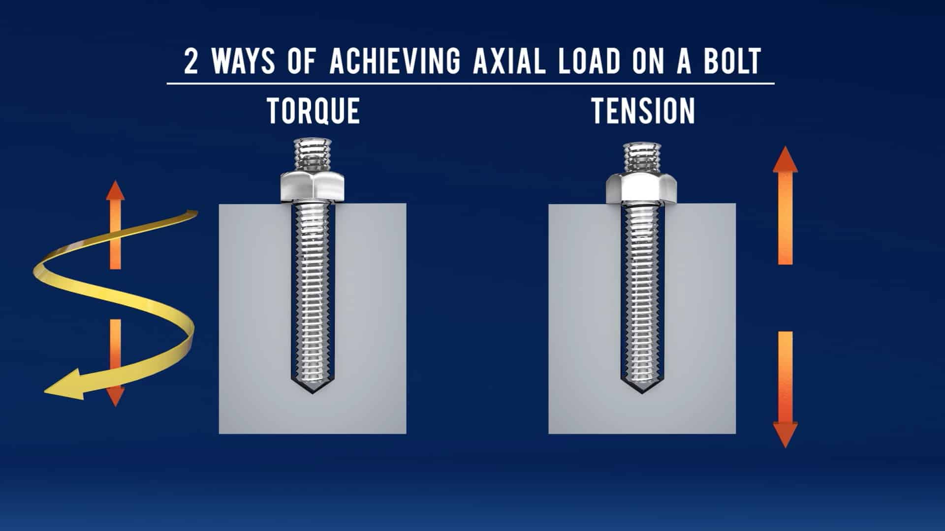
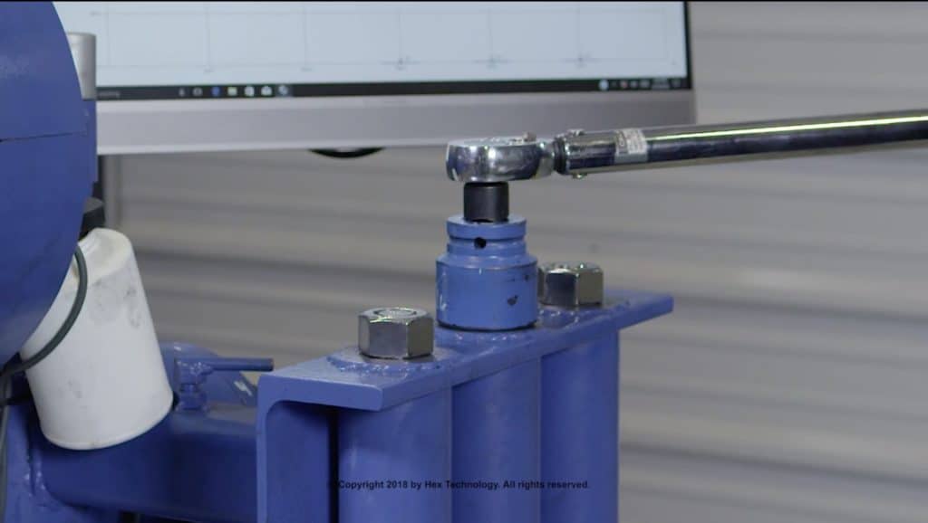
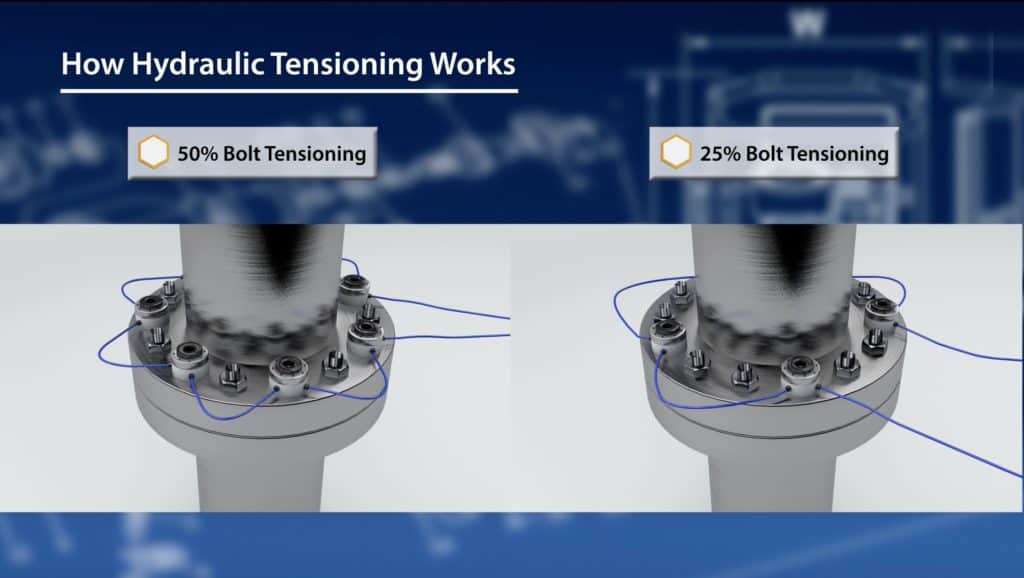
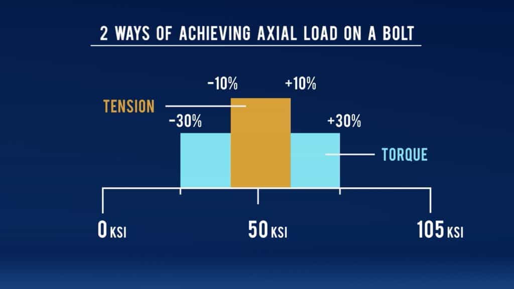

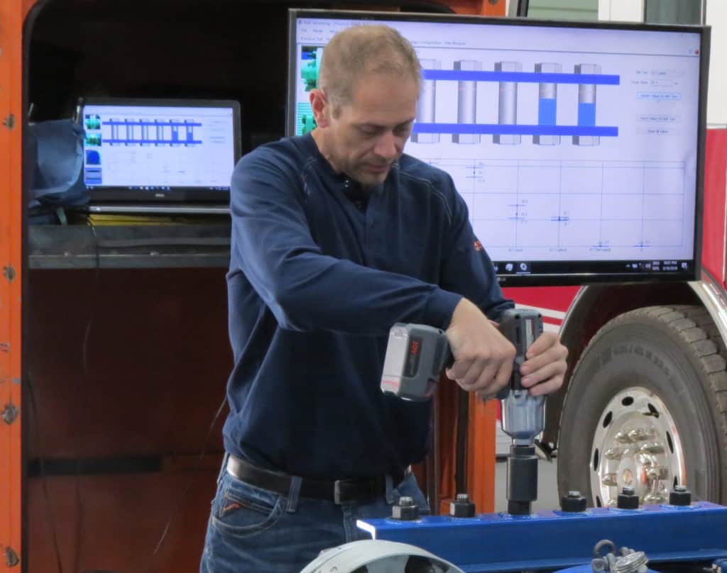
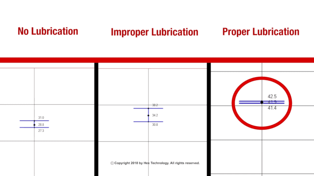
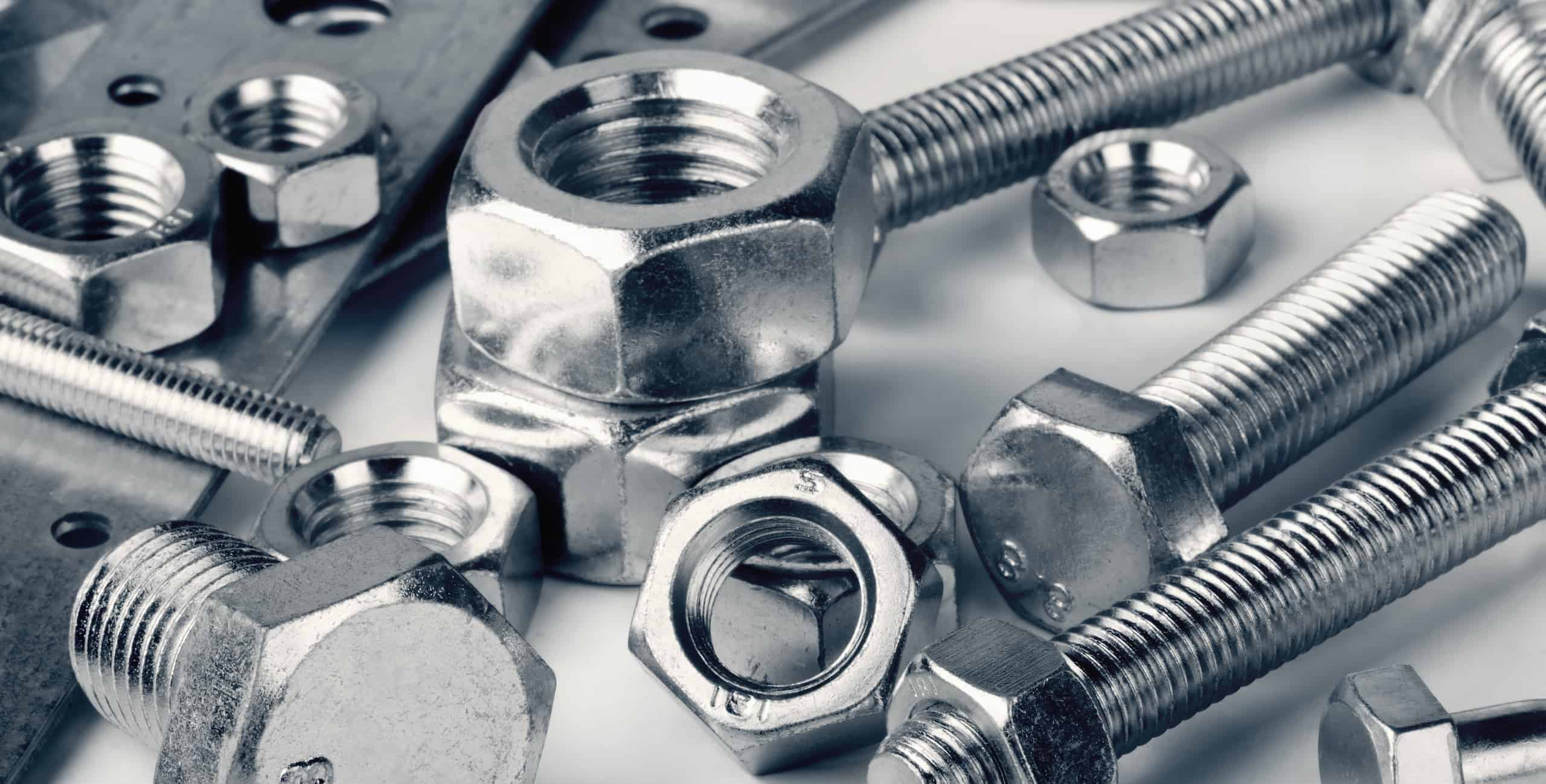
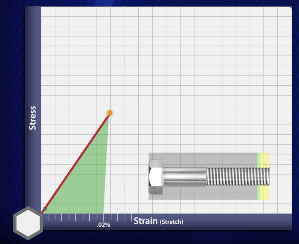
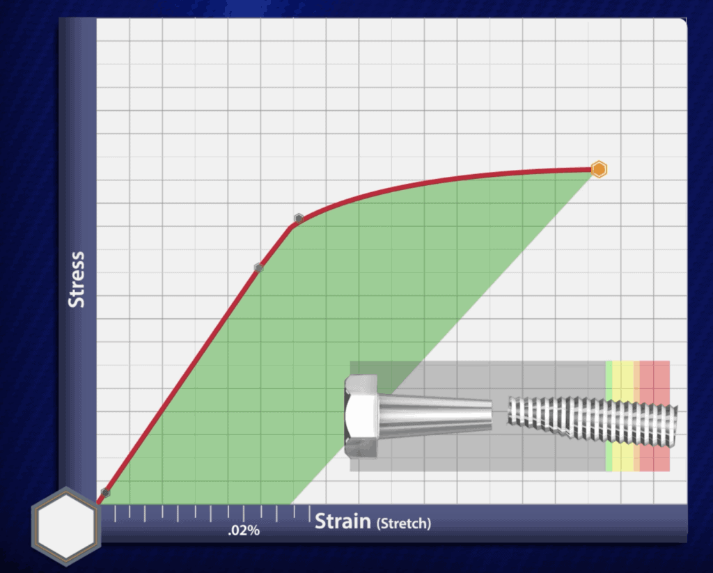
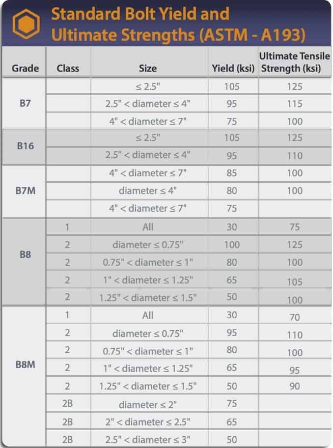
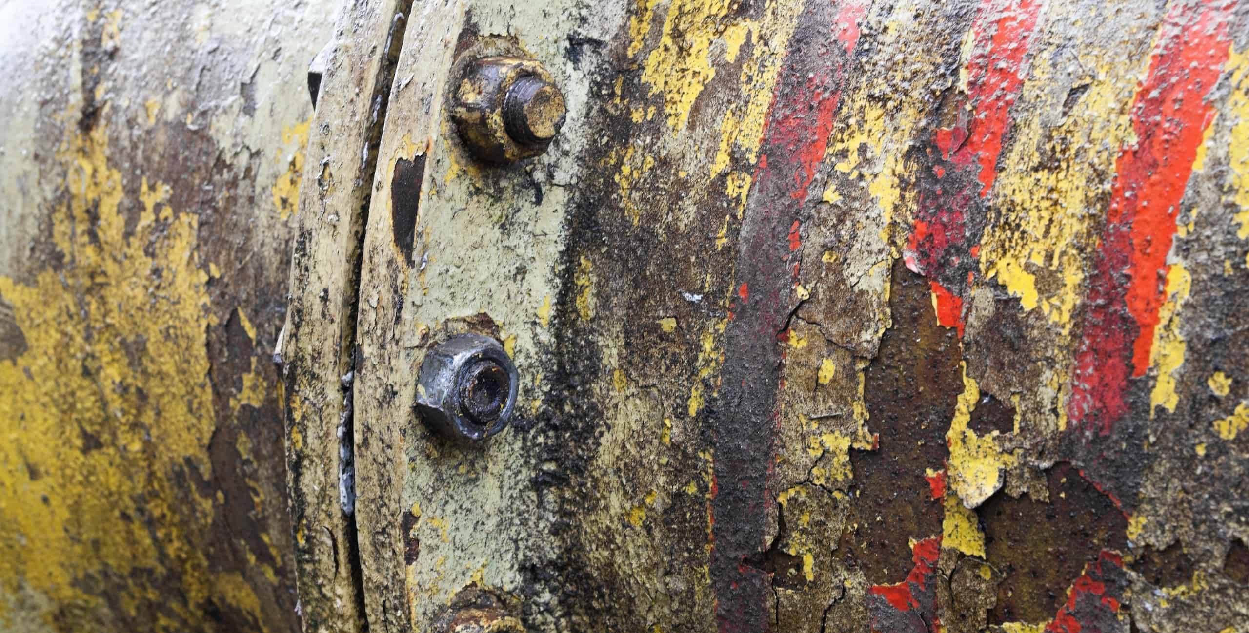
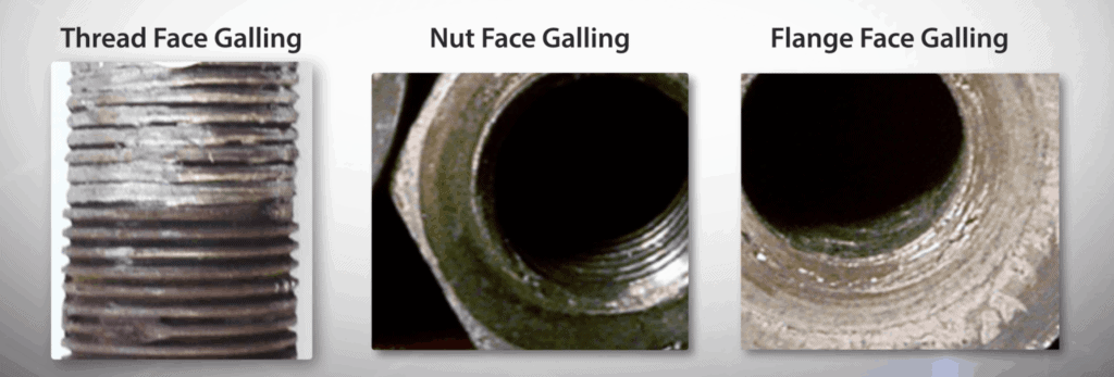
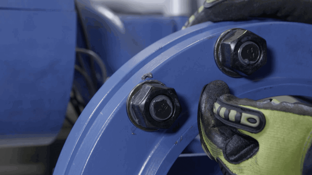
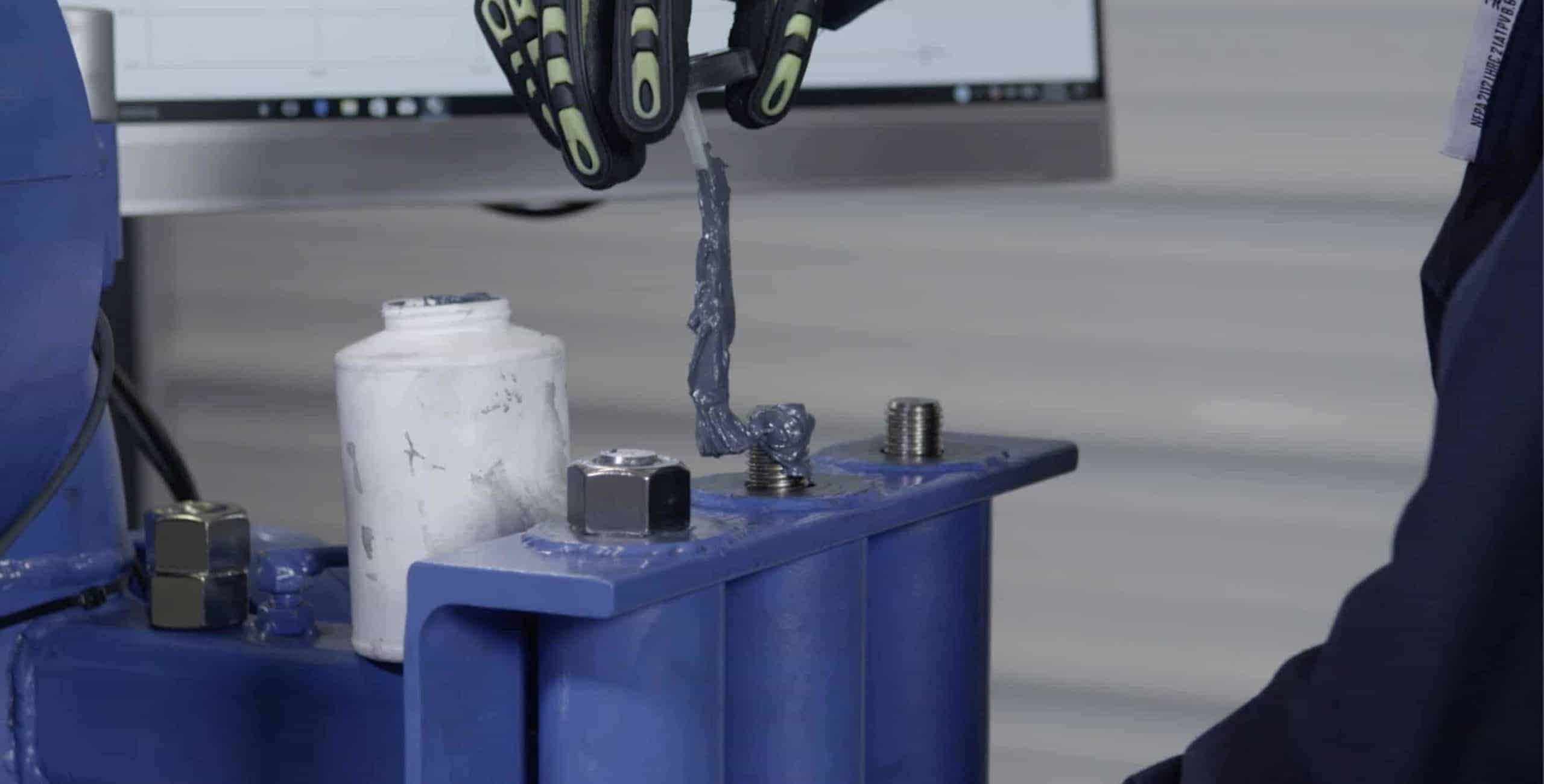
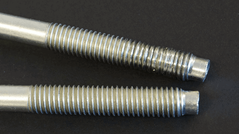
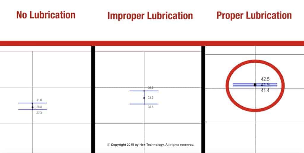
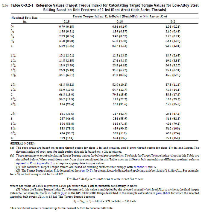
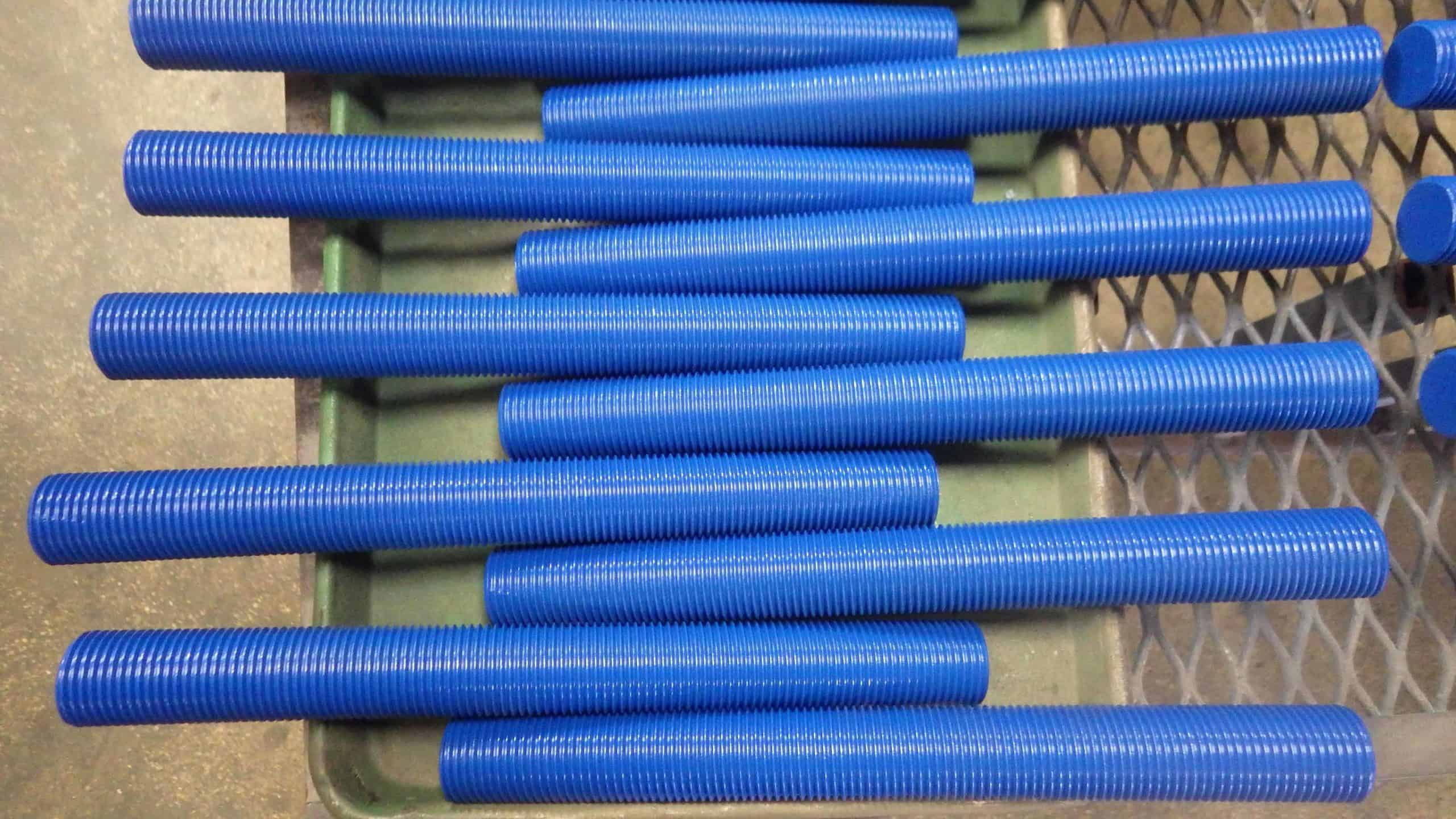
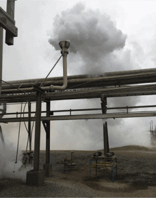 When we started researching PTFE studs, we took standard B7s, B7s coated with PTFE, and a set of B7 Doxsteel studs. We then put them in the worst part of a plant: In the way of drift from a cooling tower. (If you notice in the photo at left, you’ll see an icicle hanging above the test flanges.)