Relaxation Pass in Bolted Flange Joints

Discussing the effectiveness and necessity of relaxation pass and start-up re-torque procedure according to industry research over relaxation behavior. 

  1. Where do “Relaxation Passes” and “Start-up Re-Torque” (Hot torque) Tightening Procedure Come From?
  2. What do we Know About Bolt Stress Relaxation in Gasketed Flange Connections?
  3. Do you Lose Bolt Preload or Bolt Stress at All?
  4. Average Bolt Stress Relaxation After Bolt-Up
  5. What is Gasket Relaxation: Gasket Creep with PTFE Gaskets and Sheet Gasket Materials?
  6. Does Relaxation Happen on High-Temperature Flange Connections?
  7. Conclusion

What are “Relaxation Passes” and “Start-up Re-Torque” (Hot torque) Tightening Procedures?

Relaxation passes and start-up re-torquing procedures are used in specifications to help prevent leakage and increase sealing performance in ANSI pipe flanges, heat exchangers, and other pressure boundary joints.

Relaxation Pass: This is a circular torque pattern on a bolted flange joint assembly at the same torque value as the initial bolt torque, performed after a specific time. 

Note: We typically perform this on a gasketed flange at ambient temperature and steady-state.

Start-Up Re-Torque (formerly known as hot torque): This is also a circular torque pattern on a bolted flange joint assembly at the same initial bolt torque value as it was assembled to, only done between 250F-450F. Be sure not to do this at high temperatures since the K-Factor (some mistakenly call this “coefficient of friction”) changes after 450F!

NOTE: Since there was confusion in the industry between hot bolting and hot torquing, ASME PCC-1 has modified the name of this process to ensure clarity between the two. 

So, when do you perform a relaxation pass and start-up re-torque (hot torquing)? Are they worth every penny? 

What do we Know About Bolt Stress Relaxation in Gasketed Flange Connections?

Hex started learning about bolt stress relaxation when we first read John Bickford’s “An introduction to the Design and Behavior of Bolted Joints.” John Bickford, being the grandfather of bolting. 

We noticed first in the top paragraph that Bickford states experiments should be done before making a specification. 

Article excerpt describing relaxation in bolted joints
Taken from Handbook of Bolts and Bolted Joints – John Bickford

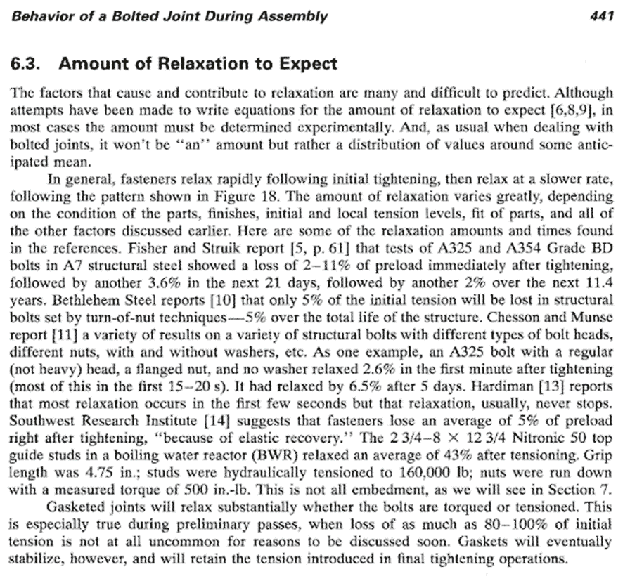
Bickford states structural steel bolts showed a loss of 11% of preload immediately after tightening and another 3.6% and the next 21 days, followed by another 2% over the next 11.4 years. 

NOTE: This applies to structural steel and not a gasketed flange joint! 

If you go down further, Bickford states that the Southwest research Institute suggests that fasteners lose an average of 5% of preload right after tightening in quotes “because of elastic recovery” (this shouldn’t be confused with elastic interaction). 

Do you Lose Bolt Preload or Bolt Stress at All?

We wanted to examine how much bolt preload we might lose to bolt stress relaxation while using metallic gaskets. 

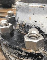
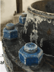
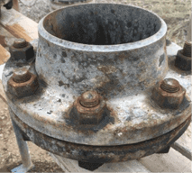
A good friend of ours, who operates a refinery, said they would give us six heat exchangers with the gaskets. We used a torque wrench to do the bolt tightening. We used UT measurement to measure the axial load and monitored the amount of relaxation on the bolted flange connections. 

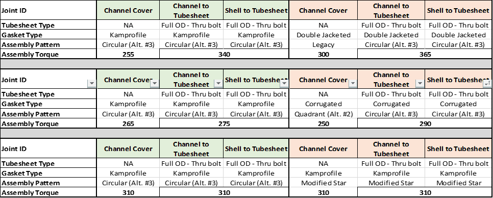
We used three different gaskets for our test: (4) kammprofile gaskets, (1) double jacketed gaskets, and (1) corrugated metal gaskets. The experiment consisted of using UT measurements on each bolt once every hour for the first day, then once a day for six days, and then once a month for the next two months.

Test results from relaxation pass in bolted flange joints

Average Bolt Stress Relaxation After Bolt-Up 

Now we get a chance to look at the data:

Relaxation in bolted flange joints after two weeks

Suppose you look at the measurements in the first eight hours, about 0.9% preload relaxation. You’ve got to remember that UT is plus or minus 3%, so we’re well within that 3%. We also see the same readings on day one, day two, and even though two weeks of monitoring. 

On average, we saw almost zero creep relaxation on metallic gaskets and no preload relaxation with standard bolt materials (ASTM B7 and B16 bolt material).

NOTE: these pressure vessels have not seen any internal pressure or high temperature!

What is Gasket Relaxation: Gasket Creep with PTFE Gaskets and Sheet Gasket Materials?

To understand this more, Hex had to go over to our friends at TEADIT and ask them to do some research on relaxation since we know sheet gaskets have gasket creep.

Jose Vega and his team at TEADIT went through and looked at when we should do relaxation passes. They used a 4″ 300# flange connected to software that shows the bolt stress on each of the bolts, measuring the bolts’ stress so we can measure relaxation.

TEADIT set the torque wrench to 120 foot-pounds and monitored the gasket relaxation. They performed a re-torque and then waited another 20 hours to record the gasket relaxation. 

Gasket relaxation in bolted flange joints

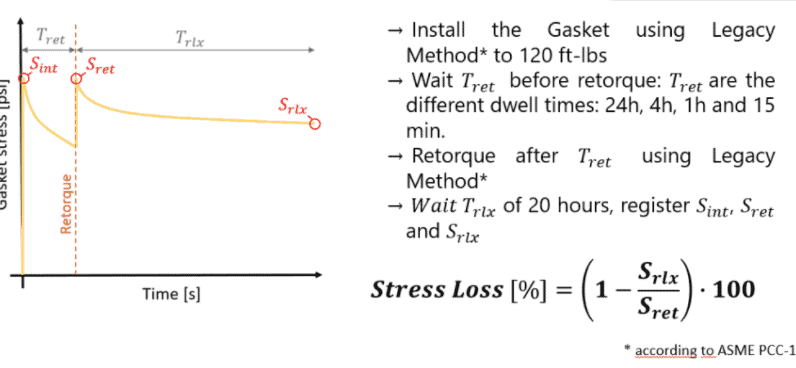
You can see these re-torque increments are: 

  • 15 minute re-torque – then wait 20 hours to measure the bolt stress
  • 1 Hour re-torque – then wait 20 hours to measure the bolt stress
  • 4 Hour re-torque – then wait 20 hours to measure bolt stress 
  • 24 Hour re-torque – then wait 20 hours to measure the bolt stress.

These are the results:

Corrugated Metal Gasket relaxation in bolted flange joints
Results of Corrugated Flexible Graphite Gasket Stress Loss
PTFE gasket relaxation in bolted flange joint
Results of PTFE Gasket Stress Loss
Spiral Wound Gasket Relaxation in bolted flange joint
Results of Spiral Wound Gasket Stress Loss

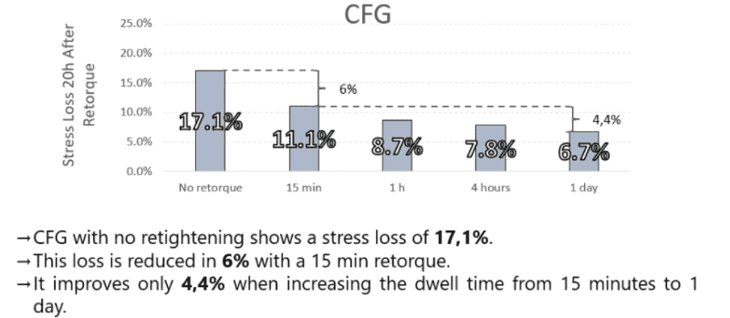
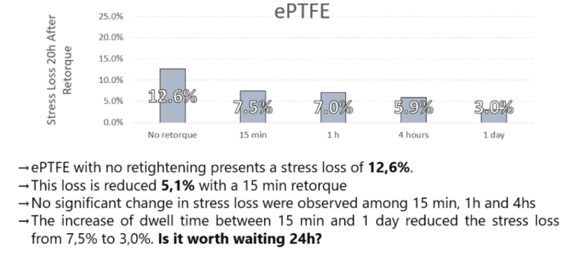
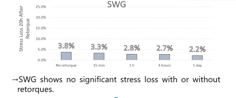
As you can see, the corrugated flexible graphite and PTFE gaskets do need a re-torque, while the spiral wound gasket doesn’t! This is because of the effect of gasket creep on the gasket thickness between the flange faces. We tend to call this “cold flow” for sheet gaskets. 

You can see that after the 15 minute re-torque, you make up a decent amount of bolt stress back. 

However, it is interesting that a re-torque after that gives back just a little bit (around 4%) of bolt stress and not as much reward as we thought it would. 

Because of this study, Hex’s recommendation is to wait an hour, go to lunch, return, and re-torque the sheet gaskets. Another practice some refineries have that has been effective for them is to have the next shift, with re-verified torque tools, re-torque the flange.

Does Relaxation Happen on High-Temperature Flange Connections?

Warren Brown and Tze Lim with Integrity Engineering Solutions (a mechanical engineering consulting firm) did an excellent study, where they presented the following information at the ASME Pressure vessel and Piping Conference. Brown and Lim looked at different ASTM A193 bolt materials at 725 degrees Fahrenheit (385 Celsius) to determine how much bolt stress relaxation one should see at that temperature.

Relaxation that occurs after high temperatures
“Quantifying Bolt Relaxation During High Temperature Operation” Warren Brown, Tze-Yew Lim

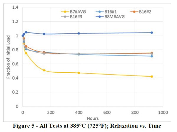
ASTM A193, B7 bolt material relaxed 60%, B16 bolt material relaxed about 25%, and the B8M bolt material gained a little load. 

Most specifications in plants that Hex works with state they upgrade bolt materials between 700F and 800F process temperature. These are good for a minimum, but if you think that high temperature is a culprit for a flange connection leakage rate, my suggestion is to look at upgrading the bolt material. 

Interesting: Hex Technology has seen that some plants put Heavy Hex nuts on B16 studs instead of Grade 4 or Grade 7 nuts. That’s a bad idea as there is relaxation in the Heavy Hex Nuts that you don’t see in the Grade 4 or Grade 7 nuts. 

Conclusion 

Question #1: Should you do a Relaxation Pass on a bolted flange joint?

Answer: Metallic gaskets do not need a relaxation pass. The amount of gasket creep is nominal and within our margin of error for measuring with UT!

Question #2: When should I do a startup re-torque on a bolted flange joint?

Answer #2: The answer to this question has two parts.

  • Part 1: I have been the guy on a live pressure vessel with a torque wrench, and it is not my favorite place. Getting a good gasket leakage buffer should be priority #1, as a slight change in gasket stress can cause a leak, and you have assemblers on the flange. So please work hard on this first. 
  • Part 2: Start-up re-torques on flange connections are great at 250F to 400F degrees. The reason why we put it in that semi-high temperature allows the bolt stress relaxation to start, AND your K-factor (not to be confused with the coefficient of friction) of your lubricant stays the same. At high temperatures, the oil burns off (at about 450 Fahrenheit), and your torque is no good…no matter how calibrated your torque wrench is! 

We typically recommend performing a bolted flange joint analysis before making these a common task in your specification. Mechanical Engineering should look at items like flange material, operating conditions, flange rotation, and possibly even do a finite element analysis to ensure you get the correct clamping force without deformation of the flanges.

Important notes

  1. At the time of this article, ASME PCC-1 is working on both definitions and guidance for “Hot Bolting,” which is now called “Single Stud Replacement.” 
  2. We did not discuss the use of washers during our experiments because they will skew the results as they increase the grip length of the studs. 

For more information about relaxation pass procedure and start-up retorque, don’t hesitate to contact us at [email protected]!

See also:

Flange Stud Bolt Lengths: What do I Need to Know?

Kammprofile Gaskets, Explained

Bolt Lubricant and Torque: A Comprehensive Guide

Flange Stud Bolt Lengths: What do I Need to Know?

Including Pipe Flanges, RTJ’s, Raised Face, and Custom Flanges

Different flange types and sizes require specific stud bolt dimensions. This article will discuss how the stud bolt length can affect flange joint assembly and how to choose the correct studs for your flange type and size.

  1. What is the Effective Length of Studs?
  2. How Does the Stud Bolt Length Affect Flange Joint Reliability?
  3. Standard ASME B16.5 and ASME B16.47 Flange Sizes
  4. Custom Flanges: Non-ANSI and API Flanges
  5. How Do I Fix the Stud Bolt Length Ratio to the Diameter of Bolts?

What is the effective length of studs?

The effective length of an ANSI stud bolt is essentially the middle of the nut to the middle of the nut. We call this the “grip length” of a fastener; this is where the majority of bolt load will reside, no matter the diameter of the bolts.

Most people think that the entire hex nut will hold the load, meaning the whole length of the stud bolts is engaged in maintaining load and gasket stress. But again, it is only the middle of the hex nuts to the middle of the hex nuts that do most of the work! 

Effective length of a stud bolt

Some people will discuss the Nominal Pipe Size (NPS), the use of metric bolts, the unified coarse pitch threads (UNC) of the bolt (or other thread pitches), or even the fact that it’s a Ring Type Joint (RTJ) instead of a Raised Face Flange affects the flange. And they are correct, but for other reasons.

For example, the 150# flange series are mathematically more likely to leak than the higher ratings found in the ASME B16.5 flange series. Why is this? Not because of the stud length, but because the diameter of bolts found in these flanges is minimal compared to the gasket; therefore, it is really hard to get good gasket stress on these flanges.

FUN FACT #1: 

8″ nominal pipe size in the 150# series flanges is mathematically more likely to leak because there is not enough bolt load than any other nominal pipe size or flange size. To increase the gasket stress, you would have to increase the number of studs or the diameter of studs. The length of the stud has very little to do with the reason these are poor-performing flanges! 

Fun Fact #2: 

3″ nominal pipe size in the 150# series flanges are the second worst for the same reason…low gasket stress. Not because of the length of the stud bolts. 

Items not covered in this article are corrosion issues, different ring gaskets, machine bolts, history of ASTM a193, and stainless steel bolt materials compared to B7 bolt materials. 

How does the stud bolt length affect flange joint reliability?

Short bolt lengths are typically less reliable than longer bolt lengths. The rule of thumb for a desirable stud length is a 5:1 ratio length of the stud to the diameter of the stud, meaning that the length of the stud bolt is five times larger than the diameter of the stud bolts. 

It doesn’t take much deflection when the bolt length is short to relieve the bolt load; however, a longer bolt length with the same spring rate will have to deflect more before the bolt load is lost. 

Therefore, when looking at the bolt circle, we want to see the length of stud bolts 5X greater than the bolt diameter. 

Standard ASME B16.5 and ASME B16.47 Flange Sizes

When looking at a standard flange (ASME B16.5 or ASME B16.47), we don’t see many flanges where the length of the stud has a ratio of less than 5:1 length of stud to the diameter of the stud. This means that we don’t see this as an issue with these types of flange sizes. 

Below is a flange bolt chart that shows that the stud bolt lengths got both ASME B16.5 flanges & ASME B16.47 flanges. It includes the bolt dimensions (including the size of the hex nuts & length of stud bolts), the different lengths of studs needed for RTJ’s and Raised Face Flanges, and the number of fasteners in each flange!

Flange stud bolt length chart

Custom Flanges: Non-ANSI and API Flanges

This becomes more of an issue when we look at custom flanges such as heat exchangers or reactors. As you can see from the video, when we drilled out the threaded tube sheet in the flange, we effectively doubled the length of the stud. Therefore this joint is more reliable when it comes to relaxation.

How Do I Fix the Stud Bolt Length Ratio to the Diameter of Bolts?

Remember, the shorter the bolt, the more deflection and the more “relaxation.” 

How do you cure this if you have a short stud bolt length ratio to the diameter of bolts? 

There are several options… our favorite is spacers for the bolts. These are the easiest to implement and use in the field. But every bolted flange joint is different, so if you would like more help, please email us at [email protected].

See also:

Relaxation Pass in Bolted Flange Joints

Flange Stud Bolt Lengths: What do I Need to Know?

Kammprofile Gaskets, Explained

How to Prevent Galling and Avoid ‘Fake Galling’

Galling, or damage to fasteners that can inhibit their movement and effectiveness, is one of the most frustrating things that bolted flange joint assemblers will run into in the field.

You’ll typically find galling takes place in applications involving:

  • stainless steel fasteners
  • fasteners that do not have anti-seize compounds applied
  • fasteners without adequate corrosion resistance materials (such as Teflon or PTFE)
  • high-temperatures
  • fasteners that have contact areas that have been damaged or contain high points

Unfortunately, there are many misconceptions about why galling (or what some call “cold welding”) occurs. Thankfully, there are several things you can do to prevent galling.

This article will explain…

  1. What is Galling?
  2. Why Galling Happens
  3. How to Prevent Galling
  4. “Fake” Galling (And How to Avoid It)
  5. Lubricants That Don’t Work
  6. Lubricants That Do Work

By the end, you’ll understand the basics of galling and have learned alternatives to help you eliminate galling through proper practices.

What is Galling?

Three forms of galling: On the bolt, nut, and flange face (from left to right)

Let’s start with the technical definition. ASTM G40 says:

“…galling is form of surface damage arising between sliding solids distinguished by microscopic, usually localized, roughening and creation of protrusions, i.e. lumps, above the original surface.”

The basic idea behind galling is that the metal from one surface ends up becoming part of the other surface. Galling occurs frequently when two metal surfaces slide against each other and high contact pressure builds.

As shown in the image above, galling can occur on any of the metal surfaces involved in bolting, from the bolt itself, to the nut, to the flange face.

(Related: See other great resources for learning the fundamentals of bolted flange joint assembly and design.)

Why Galling Happens

There are many theories about why galling occurs. Not all of them are true.

Here are a list of the most commonly cited culprits. We’ll identify which are true, which are false, and hopefully end some conspiracy theories along the way.

Lack of Proper Lubrication (Anti-seize)

Proper anti-seize compounds are the best way to prevent galling between mating surfaces. A typical anti-seize compound contains about 60-70% solids. At high temperatures (about 400 degrees F), the remaining oil burns off, leaving the solids to protect from galling.

Anti-seize should be applied through the entirety of the thread surfaces, so that when the nut is rotated to the flange, a bead of lubricant “squishes” out the bottom of the nut surface (as shown in the image below).

When bolt lubricant is properly applied, a little bead will squish out whenever two surfaces come into contact.
Properly applied bolt lubricant. Note how the light gray lube “squishes” out between the black bolt and nut.

Use of Spray Film Lubricant

We DO NOT recommend using this lubricant. It doesn’t give you a consistent K-factor, which will negatively affect your bolt preload, and it does not have enough solids to sufficiently prevent galling.

Nickel Anti-Seize vs. Molybdenum Disulfide Anti-Seize

Nickel is not a great lubricant for bolted flanged joints in petrochemical applications, because nickel is a metal. Remember: In applying pre-load to a fastener, an assembler is essentially grinding metal on metal. Adding in another metal (nickel) can actually worsen the situation.

What you really want is a mineral to act as a barrier between the contact and mating surfaces. Molybdenum Disulfide is a mineral and will help prevent galling better than a nickel anti-seize.

NOTE: With the friction and high temperatures seen during torque and operation, Nickel anti-seize creates nickel oxide, a very hard particle that will actually scar the material.

Stainless Steel Bolts and Stainless Steel Nuts

These are often the worst offenders for galling. Some believe this is due to their having a softer material and high alloy content. We don’t have great information showing stainless steel fasteners being more susceptible to galling, but we see it a lot in the field.

Corrosion Applications

These fasteners typically have an outer coating (like PTFE) on the outside of the initial protective oxide coating to provide corrosion resistance. However, if you read our PTFE article you will see that the nuts have been drilled to allow for a greater thread allowance between the nut and stud to accommodate the coatings.

NOTE: You should always lubricate PTFE coated studs because at preloads of 30,000 psi or more, the coating will tear off and you will lose your corrosion resistance. Applying anti-seize to the fastener will help protect the stud.

High-Speed Torque vs. Slow-Speed Torque

We have seen no correlation between high-speed or slow-speed torque and galling, so long as the fasteners have had the proper amount of anti-seize applied.

Fine Thread and Coarse Threads

There’s no good data that shows whether fine threads or coarse threads are more prone to galling. What we do often see, however, is that coarse threads are typically used in places where proper amounts of anti-seize are not used (such as structural steel applications).

How to Prevent Galling

The number one thing you can do to prevent galling is to properly apply the anti-seize to the thread surfaces where the anti-seize fills the entire fastener valleys.

We have an example below in the video of what proper lubricant application should look like:


Another way you can prevent galling is to tension (instead of torque) the studs. Then they won’t see the friction inherent in torque and will be less susceptible to galling.

What is “Fake” Galling?

“Fake” Galling happens more than most assemblers would like to admit.

Most of the time, galling occurs on large fasteners (two-inch studs or larger) that are attached to large flanges (plates that are 5 inches or thicker).

Why is that?

It’s due to elastic interaction. This is what happens when you drop the load on one fastener — the other fasteners actually see an increase in bolt load.

What happens next? Most of the time, you’ll put your wrench on the second stud — and find it doesn’t move. The immediate reaction is that the fastener has galled. That’s fake galling in action.

Here’s how to prevent fake galling:

  • In a circular pattern, loosen the fastener by 1/2 flat of a nut all the way around the flange.
  • In severe cases where galling has occurred before, continue with one more round of 1/2 flat of nut rotation, before you completely unload any fastener.
  • This will gradually unload the fasteners and reduce the chance of fake galling happening.
  • NOTE: You MUST do this in a circular manner, not in a star pattern. If you do it in a star pattern you will see that every other stud will have added stress to it, and this won’t work.

Lubricants That Don’t Work

As we discussed earlier, to avoid galling you’ll want to stay away from spray lubricants and nickel-based anti-seize. However, you must ensure that the anti-seize compound that you are using is safe for your application.

Remember: PTFE-coated studs (either Xylon(R) or Teflon(R)) are good for corrosion resistance, but they do not have a good K-factor. You should add anti-seize when assembling them, so long as doing so won’t contaminate the process.

Lubricants That Do Work

Hex Technology has seen that a good molybdenum disulfide lubricant is the best for petrochemical applications. We have had success using these in other industrial settings as well.

Related Articles:

A Comprehensive Guide to Bolt Lubricant

A Guide to K-Factor

PTFE Coated Studs: Do They Work? 

Join Industry Leaders!

Subscribe to Hex Technology today and we’ll give you $700 in bolting courses, FREE. Your path to a safer, more reliable, more profitable site starts here.

  • This field is for validation purposes and should be left unchanged.

PTFE Coated Studs: Do They Work?

PTFE Coated Studs: A Little Background

PTFE is short for Polytetrafluoroethylene, a chemical applied to common bolting materials (such as B7 stud bolts) to provide corrosion and chemical resistance.

Some other common coatings for PTFE coated fasteners are Teflon® and Xylan®. In this article, we’ll refer to all of them as PTFE.

PTFE coated studs have been used for many years within the bolting industry, especially in any application that requires corrosion resistance or in offshore applications (salt spray is hard on Grade B7 material). PTFE is also useful if you’ve had “galling” and need a lower breakout torque for safe removal.

PTFE should not be used in high-temperature applications. Fluoropolymer coatings manufacturers use temperatures in the 400F-500F as the maximum temperatures, so you typically do not see alloy steel bolts (such as B8) with PTFE coatings.

While PTFE coated studs (including Xylan® coated studs) have corrosion-resistant properties, which are functionally understood by assemblers, the technical aspects of fluoropolymer coatings are often misunderstood.

For example, as an assembler, I was told that the PTFE coaching acted as a lubricant, which meant I didn’t have to mess with lubricating them after I put them into a flange.

It sounds like the perfect solution. The only problem is: That advice was wrong.

Way wrong, in fact.

Yet many front-line assemblers today still think it’s correct.

Thankfully, in the decades since I first started putting together flanges, smart minds both in the lab and on the front lines have given us a much more accurate picture of how PTFE coated studs work.

In this article we’ll bust some myths, provide practical advice, and address some of the most common questions we hear from craft assemblers today, including:

  1. Are all PTFE coated studs the same?
  2. Do I lubricate PTFE coated studs?
  3. Can I re-use PTFE coated studs?
  4. Why do PTFE studs have low friction and lower break out torque than regular studs? (Grade B7 with 2H hex nuts for example)
  5. Does the PTFE coating help with corrosion resistance?

Click any of those questions above to jump directly to the answer you want. Or read on to get the complete picture of how PTFE coated studs affect assembly.

1. Are all PTFE coated studs the same?

Absolutely not.

While PTFE is the same as Teflon® on a chemical level, they are not applied the same way by each manufacturer. There also are several different types of base coats.

Therefore, the thickness of the coating on the fastener is not a standard — and quite frankly, it’s not controlled.

As a result, you must choose one manufacturer and test your k-factor for their product, and recognize that those values do not transfer to other PTFE coated stud manufacturers.

2. Do I lubricate PTFE coated Studs?

Yes!

At 30,000psi bolt load (not to be confused with 30% tensile strength), you start stripping your coating. Also, the coating will start binding. Therefore, you’ll have better accuracy and less bolt scatter (or differences in bolt loads on each bolt) by using lubricating them.

However, you will have to test your lubricant and manufacturer combination in order to correctly determine your K-Factor. Note: Don’t confuse K-Factor with low coefficient of friction, which is not used for this calculation.

(Learn proper lubrication techniques in our Level 1 course — now available free.)

3. Can I re-use PTFE coated studs?

You shouldn’t.

If you were to re-use PTFE coated studs, the corrosion-resistant coating on the threads will most likely be at least somewhat degraded or damaged, meaning your K-Factor will change again.

Physically the bolt might still hold up to corrosion. So visually, they would still look good, which would lead someone to think that the life expectancy of the stud would be longer. But appearances can be deceiving, and you shouldn’t reuse PTFE coated studs.

4. Why do PTFE studs have low friction and lower break out torque than regular studs?

What would you say if I told you that, in order to fit the nut on the stud with the PTFE coating, you must drill a bigger threaded hole (tap) through a 2H nut? Yes, it’s true. And there is are no technical specifications on this.

I couldn’t believe it either, but you will be effectively taking 30%-50% of the contact surface away. Therefore, it is not the PTFE that makes it easier to disassemble (and you have a low friction between stud and nut on assembly). This phenomenon is due to having considerably less contact area!

5. Does the PTFE coating help with corrosion resistance?

Yes…to an extent.

Let’s say you have a B7 stud (ASTM A193) and 2H nuts. The application process and proprietary materials of the PTFE coating is intended to help with corrosion resistance. However, since the coating is proprietary to the manufacturer, it is hard to say how well it helps with corrosion resistance.

One way to test this is with a salt spray test with ASTM B117, which sprays the stud bolts up to 3,000 hrs while not freezing the nuts.

A Brief History of PTFE

Before PTFE coated bolts came along, the petrochemical industry used other methods of making corrosion-resistant bolting components, such as hot dip, galvanized, cadmium or zinc-plated fasteners.

Polytetrafluoroethylene (PTFE) is a synthetic fluoropolymer of tetrafluoroethylene that has numerous applications. The most well-known brand name of PTFE-based formulas is Teflon by Chemours. Chemours, a spin-off from DuPont, originally discovered the compound in 1938.

PTFE (polytetrafluoroethylene) coatings are considered non-stick coatings. Therefore you need a process to apply the “non-stick” coating to the “B7 stud material”. Therefore, the typical manufacturing process is a three-step process.

  1. Apply a corrosion resistant base coating
  2. Apply an adhesion coating
  3. Apply a polytetrafluoroethylene nonstick topcoat

It’s unclear exactly when the bolting industry started using PTFE coated studs, but they have been around for a while. They tend to be used in highly corrosive environments.

Once the bolts prove themselves, people start placing them all around the plant — regardless of whether or not they should or need to.

Bottom Line: I am not very fond of using PTFE coated studs as it increases the complexity of a bolted joint, you don’t have a consistent K-Factor (not “low coefficient of friction”). Unfortunately, PTFE coated studs are over-prescribed since most people don’t know how they actually work.

A Real-World Test of PTFE

A cooling tower pours condensation onto our test bolts. 
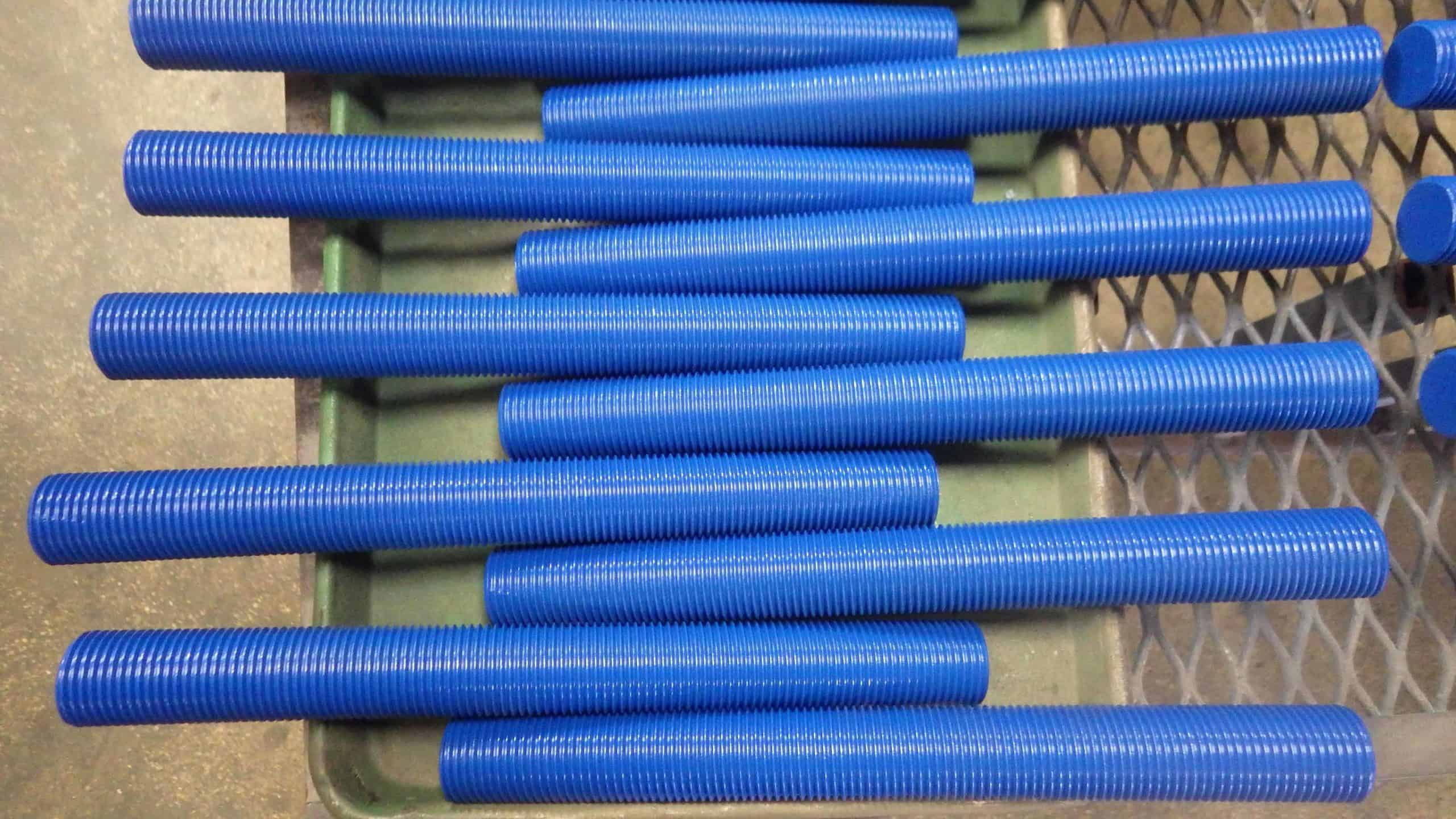
When we started researching PTFE studs, we took standard B7s, B7s coated with PTFE, and a set of B7 Doxsteel studs. We then put them in the worst part of a plant: In the way of drift from a cooling tower. (If you notice in the photo at left, you’ll see an icicle hanging above the test flanges.)


Here’s what happened:

b7 studs with doxsteel coating during a corrosion test B7 studs with a PTFE coating during a corrosion test. Standard B7 studs during a corrosion test.

(From left: B7s coated with Doxsteel, B7s coated with PTFE, and standard B7s.)

So, out of the three pictures above, which would you say has the easiest break-out torque (some call it a low kinetic friction coefficient)?

My thoughts were: Doxsteel, PTFE, and then B7 studs.

Nope.

The B7 studs with PTFE were easier to break loose. I asked the CEO of Doxsteel about the testing, and why his studs were second best, and this is what he showed me.

Oversizing Nuts to Make PTFE Studs and Nuts Fit

One of the biggest issues in bolting is K-Factor, as it deals with how the friction when applying torque and proper lubricant will help with safe removal of the studs during disassembly.

We’ve found through testing that at about 30,000 psi of bolt load, you start to tear that PTFE coating off the stud and heavy hex bolts. (Learn more about high psi applications in our free course on Powered Equipment.) The coating ends up binding on the bottom of the nut and threads. This changes the binding of the PTFE, makes the K-factor change, and your bolt scatter is more dispersed.

Why does this happen? Well, it works together with a lower break out torque. The nuts are over-tapped!

Yup, as you can see in the picture on the top above, you will see normal engagement of a B7 stud. Then the picture on the bottom shows how PTFE manufacturers over tap the nut so that the coating can fit.

You can normally see 20%-40% less engagement of the threads. So it is not the PTFE that makes it easier to break loose, but actually the lack of engagement!

Other References to Review

It’s hard to find material on this topic that wasn’t published by a manufacturer. But here are a couple of interesting resources:

  1. Doxsteel. These guys are responsible for the pictures above and testing with Hex.
  2. Here’s a video I found on the application of PTFE. I can’t confirm, but I think that this is how all manufacturers apply it (which seems less technical than I ever thought).

RELATED: 

Bolt Lubricant and Torque: A Comprehensive Guide

How to Prevent Galling

K-Factor: Let’s Clear Up Some Things…

Join Industry Leaders!

Subscribe to Hex Technology today and we’ll give you $700 in bolting courses, FREE. Your path to a safer, more reliable, more profitable site starts here.

  • This field is for validation purposes and should be left unchanged.

Bolted Flange Joint Assembly: Learning the Technical Aspects

In 2005 I started selling hydraulic torque wrenches. Like many young salesmen, I instantly thought I was a “Bolted Flange Joint Expert.”

(Today I consider myself a recovering Bolting Expert.)

When customers asked about how flanged joints worked, my go-to response was, “well, target torque is the only thing that matters.” I didn’t consider things we now know are essential, like…

  • assembly procedure
  • tightening sequence
  • the guidelines in ASME PCC-1

I just looked at bolt stress (really, the percent yield of the stud), and a little bit on the “cross pattern” (a.k.a. the star pattern), but that was it. If you gave me a torque value or bolt load, I wouldn’t necessarily know why or how it was generated. I just knew how to apply the tightening method to the appropriate fastener size.

What “Bolting Experts” Often Miss (or Misunderstand)

It’s a problem that still occurs today. Despite being one of the oldest assembly practices in industry, bolting techniques are often learned on-the-job, delivered from seasoned assemblers to greener staff. While this may cover some of the basics, word-of-mouth training often fails to address fundamental concepts such as…

And really, that’s just the beginning. The field of bolted flange joint assembly goes far deeper. More than 15 years later I’m still learning new things about bolted flange joint assembly (BFJA).

Often, I get asked a question that was on my own mind back at the beginning: “Where can I go to learn about BFJAs (both pipe flanges and heat exchangers)?”

Best Resources for Understanding Bolted Flange Joint Assembly

A close up of bolts in a bolted flange joint.

There are good authors and publications, and bad ones, within bolting. I’m not going to waste your time by listing resources that aren’t worth reading. Instead, I’ve collected materials about the past, present and future of the bolting industry you ought to know. However, this list is always growing so don’t just stop here!

(NOTE: These books are for references to concepts. They aren’t a recipe for the assembly of BFJA’s or proper flange assembly practices.)

The Classics: John Bickford is the first author of BFJA books. Some of the material is outdated now, but they still are good reference material. He has three and the below listing is in order and not rank with a description of each book. They are not cheap ($200+ each) and you can find them both on Amazon:

  • An Introduction to the Behavior of Bolted Joints – This is the first book he published. It’s my second-favorite of his works because it talks about basics but the book that followed it (listed below) has a better scope of concepts.
  • Handbook of Bolts and Bolted Joints – Bickford takes his best articles from his first book and adds about 30 more articles from what were then “trusted resources” within the industry. Some of the articles are a little biased since they were written by the manufacturers of the products, but it will give you a good idea of how each topic functions.

The Present: The American Society of Mechanical Engineers (ASME) has published PCC-1 (Post Construction Committee -1) which is titled, “Guidelines for Pressure Boundary Bolted Flange Joint Assembly.”

This is the industry standard on how to assemble BFJA’s and is great for calculating gasket stress, K-Factors, training, etc. One should be very familiar with this document and is a good jumping point for a holistic understanding of bolted flange joints.

You should also read “Welding Research Council Bulletin 538” which has the background on many topics in ASME PCC-1.

For Upstream Applications, you should also read through API 6A.

Also for the Present: My new favorite book that has been updated frequently is published by Jose Veiga and it is titled “Industrial Gaskets.” You can download it for free at that link.

The Future: The American Society of Mechanical Engineers has an annual conference where BFJA’s receive their own section. You can find the research being done here.

Refine the search to “Bolted Flange Joints,” then narrow down by author. I highly recommend Dr. Warren Brown, who was my engineering mentor and is widely regarded as the foremost expert in the world on bolted joints today. However, you can filter by your topic and author on whatever you might be looking for.

NOTE: These articles normally cost $25 each.

Conclusion: BFJA Essentials

Today there are still many people in the BFJA industry who claim to be “experts.” Most are…on own products. But many of these individuals don’t possess a holistic understanding of all the parts that go into proper bolted flange joint assembly.

After many years of reading through the work of these experts and their opinions, I’ve found that sticking to the basics is the best path. Therefore, my recommendation is to follow ASME PCC-1 guidelines as the standard and use the different references to understand the items in ASME PCC-1. (Find more on ASME PCC-1 Training, and how to use it in your organization, here.)

When you research these topics, please remember: Keep it simple. Also, beware if someone tells you any of the following:

  • “We have had 100% success…” (<-No, no you didn’t.)
  • “This product brings together the best from X product and Y product…” (<-If it brought together only the “good,” where did the “bad” go?)

Also remember: You can’t out-procedure a lack of training. ASME PCC-1 Appendix A discusses the joint assembly procedures that all bolted joint assembly personnel should know, and serves a good syllabus for all individuals associated with BFJA’s to understand.

RELATED: Read our guide to clicker-type wrenches.

Join Industry Leaders!

Subscribe to Hex Technology today and we’ll give you $700 in bolting courses, FREE. Your path to a safer, more reliable, more profitable site starts here.

  • This field is for validation purposes and should be left unchanged.