Hex Technology conducted a torque tool calibration and verification study with a small refinery. In this study, we analyzed the different types of torque tools used during a turnaround and the accuracy of the calibration process. We concluded that regular verification of calibration in torque tools may be a necessary part of the QA/QC process.
- What is Torque Tool Calibration and Validation?
- Frequently Used Terms when Discussing Torque Wrench Calibration and Validation
- Development of the Calibration and Torque Wrench Verification Knowledge
- What Torque Tools are Being Used in the Industry?
- How Often Should I Calibrate a Manual Torque Wrench?
- How Often Should I Calibrate our Power Tools?
- How did Hex Come to These Conclusions for Torque Validation?
- Method of Verification
- Torque Verification Recommendations
- Conclusion
What is Torque Tool Calibration and Validation?
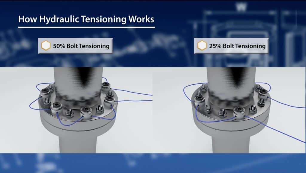
Calibration of torque wrenches is critical to the reliability of bolted flanged joints when using torque measurement to achieve axial load on a fastener. While ISO 6789 has a proven method of calibration for manual torque wrenches (commonly called “clicker” type torque wrenches), there is no current popular method of calibration for “Powered Equipment” seen in the industrial world.
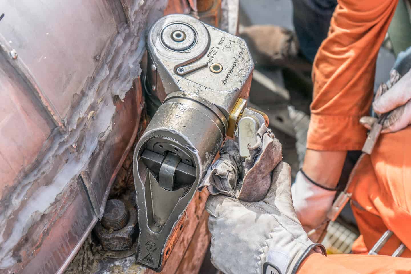
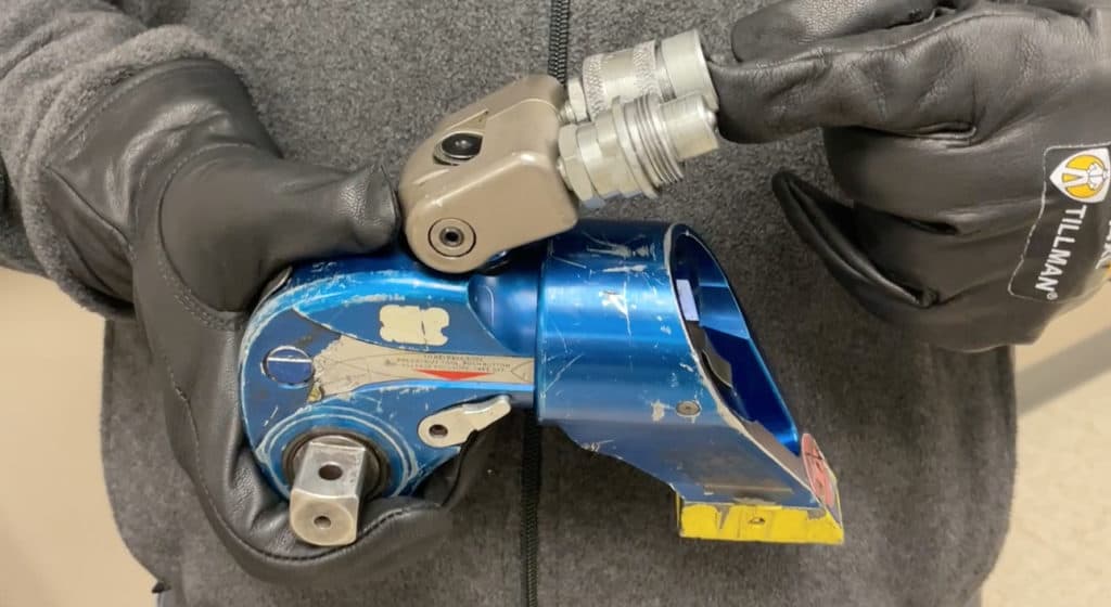
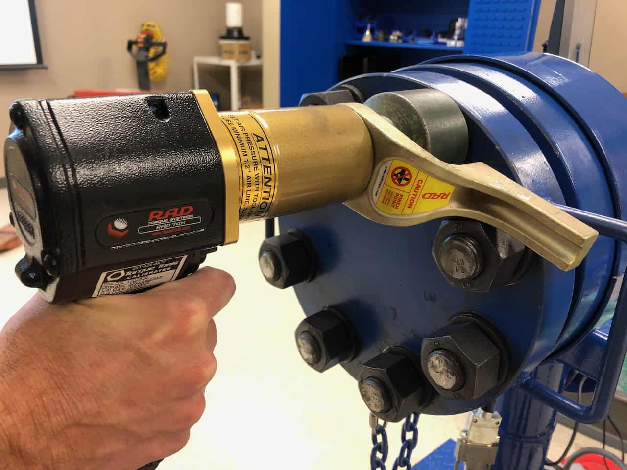
These power tools include pneumatic torque wrenches & battery torque wrenches (we consider these pistol grip torque multipliers) and hydraulic torque wrenches. These torque wrenches typically have a torque range from 500 ft-lbs to 5000 ft-lbs.
Torque validation is when we double-check the accuracy and repeatability of the torque setting on a given torque wrench. We can also use this validation process to audit and examine calibration labs and service companies.
Note: We do not talk about torque screwdrivers, metrology used for calibration, and what adapters do to change the torque value.
Frequently Used Terms when Discussing Torque Wrench Calibration and Validation
There is some dirty laundry that we should wash out before we get to the remainder of this paper. Here are some words that calibration labs and service companies who provide torque wrench calibration fly around:
- ISO 6789 is a calibration standard but only applies to manual torque wrenches. It DOES NOT address Powered Equipment. But it is solid for manual torque wrenches and is commonly used by calibration service companies.
- ISO/IEC 17025: The ISO website says, “ISO/IEC 17025 enables laboratories to demonstrate that they operate competently and generate valid results, thereby promoting confidence in their work nationally and worldwide.”
- Note: Just because a calibration lab has this accreditation, it does not mean that they calibrate the torque wrenches correctly! It just means that they are doing what they say they are doing…even if it isn’t correct.
- Shocking fact: Most torque wrench manufacturers do not have a calibration standard for their torque tools that they impose on calibration labs! So how can you judge the “valid results”? Only through proper validation of the procedures, which we have not seen much of in the industry.
- NIST Traceability: Calibration labs will have torque transducers with a certification for NIST (National Institute of Standards and Technology). While this is important, it means that the torque transducer has been calibrated correctly by proper calibration equipment, not that the actual torque wrenches have been calibrated correctly.
- Calibration Certificate: These are great to have, and typically calibration laboratories do a great job on the technical aspects of what they know. They include the NIST traceability of the torque transducer, the confirmation of applied torque achieved, and all the ISO/IEC 17025 accreditation details. But again, how did they develop their calibration methodology, considering there is no standard for power tools? Have they ever put their methods to test on a fastener?
Development of the Calibration and Torque Wrench Verification Knowledge
Multiple papers have addressed the different aspects of calibration for Powered Equipment, and we list them at the end of this paper.
The questions that we have not been able to answer through previous tests that we were looking at answering with this test are:
- What types of torque equipment are used within the petrochemical industry, and what frequency?
- What is the calibration or torque testing frequency that each wrench should undergo?
While each plant and industry are different, this paper will address these questions based on over 8,000 data points from a refinery turnaround and feedback from manufacturers of power tools.
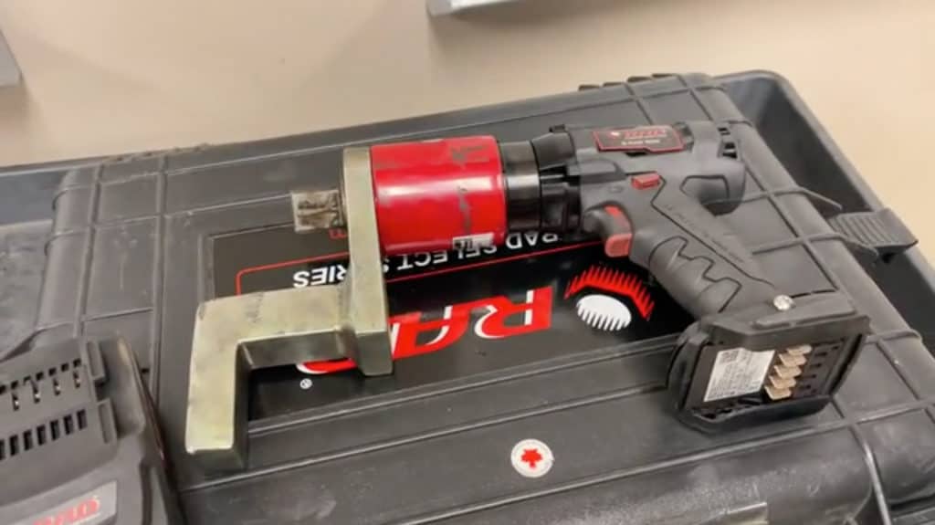
What Torque Tools are Being Used in the Industry?
In a previous YouTube video we made, we went in-depth about the most used torque tools in the industry during turnarounds. We gathered information from some of our clients that oversaw turnarounds at their plants.
We discovered in that research that 80% of torque tools used during the turnaround were square drive manual torque wrenches and pistol grip tools (pneumatic and battery-powered).
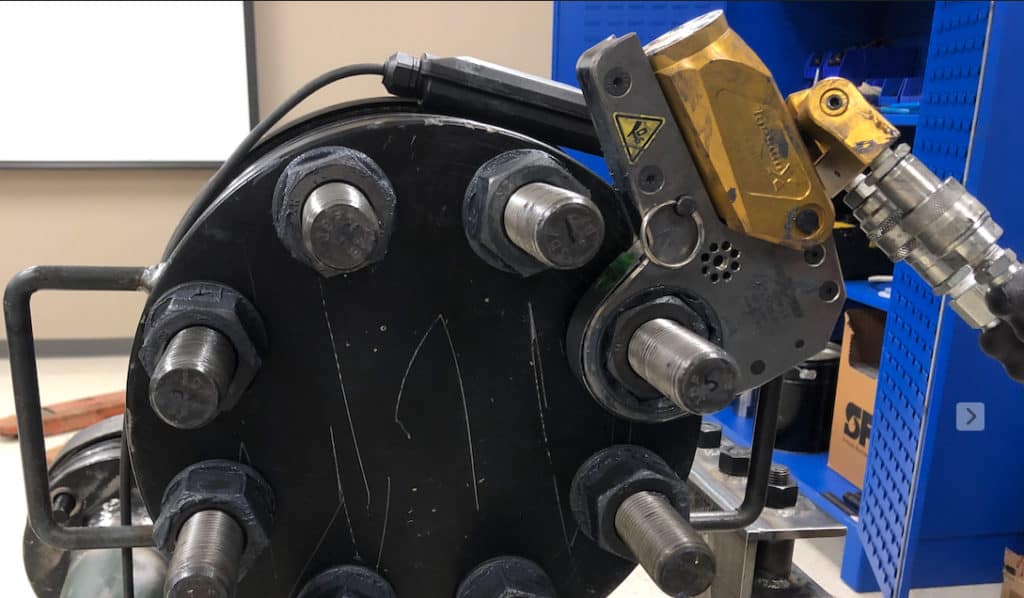
20% of the tools used in that study were the hydraulic torque wrenches, including square drive and low profile tools. We are going to concentrate on the 80% as of now!
How Often Should I Calibrate a Manual Torque Wrench?
ISO 6789 states that manual torque wrenches shall be calibrated once every 12 months. But our previous studies have shown that roughly 60% of manual torque wrenches will be out of calibration at the end of 12 months.
How many fasteners did that torque wrench touch while out of calibration? There is no good way to tell.
Therefore we found that there are torque testers that you can deploy either in your shop or out in the field to validate the torque values! And they are not too expensive.
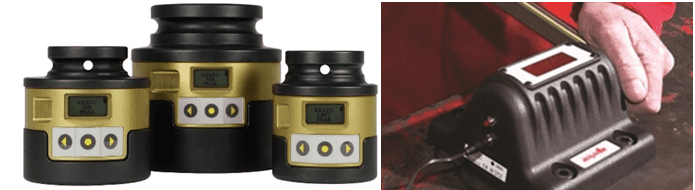
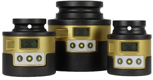
The one that we have the most experience with is the NORBAR TruCheck. They have several models out there, but our recommendation is to get one that will do roughly 500 ft-lbs so that all of your manual torque wrenches can be validated.
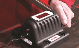
Another torque verifier that we have found works great to verify powered equipment or can even be brought into the field to verify the accuracy of torque on the flange is a Smart Socket.
- Note: Hex Technology does not get paid if you buy these. This info is what we have found to help out our customers. If you know of another one that we should look into, please contact us at [email protected].
How Often Should I Calibrate our Power Tools?
Until the industry standardizes on a calibration verification method, End Users can use the tools to assess/audit their suppliers to see if their accuracy and calibration method are enough to meet its requirements.
We have found that any method of calibration or verification should be compared with the flange setup that has been written about in previous papers.
How did Hex Come to These Conclusions for Torque Validation?
In the past, the Maintenance Manager from a small Midwest refinery had allowed each contractor for a turnaround to bring their own torque tools for use. After working with Hex Technology for the past three years on the accuracy and repeatability of torque wrenches, they decided that their refinery would supply all the torque wrenches for the turnaround to improve calibration consistency.
Two central tool trailers were set up in the refinery, one of which was for the hydrofluoric acid (HF Trailer) plant, and the other was for the rest of the plant (Main Trailer), which a chosen vendor staffed. The HF trailer data is not included in the findings here as they were primarily clicker-type wrenches, and this study focuses on Powered Equipment.
The Main Trailer was equipped with transducers to work on manual “clicker” type (clicker) wrenches and hydraulic wrenches.
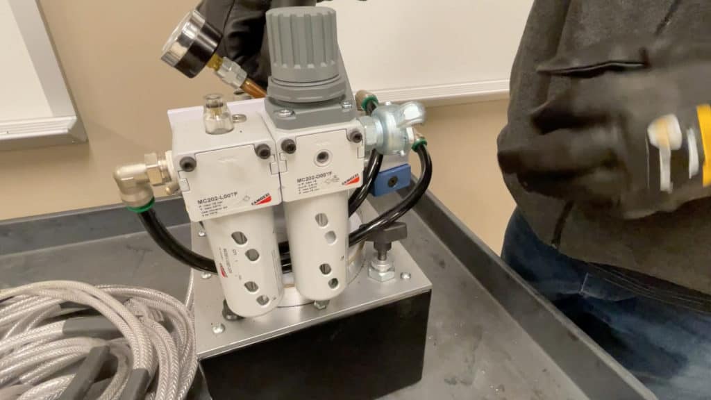
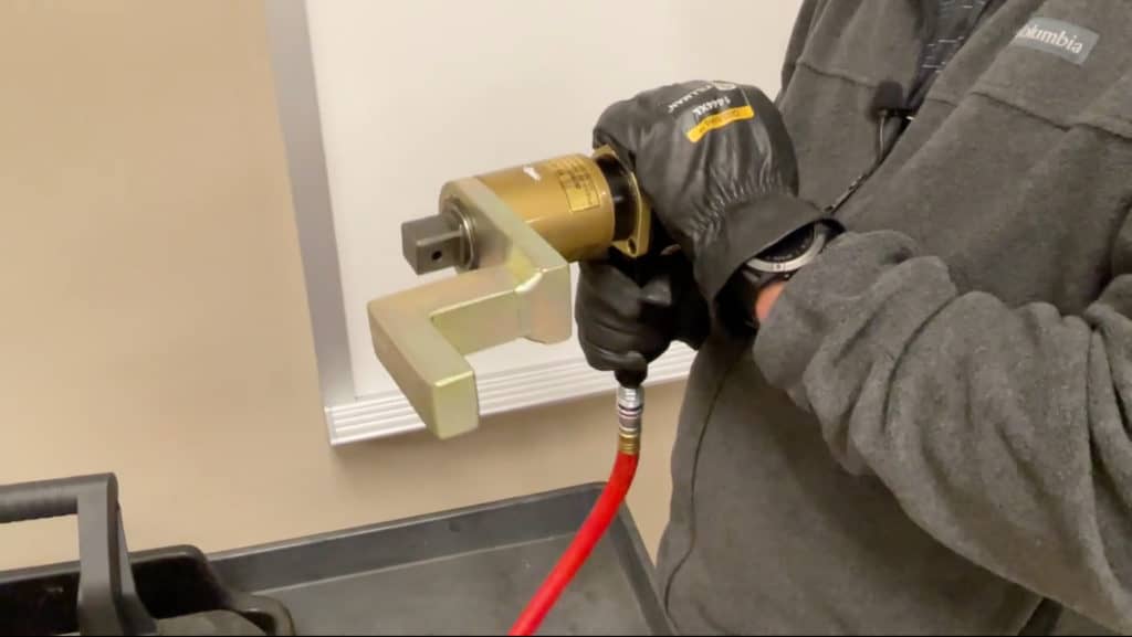
The pneumatic and battery-powered torque wrench vendor provided a new calibration system for pneumatic, and battery-powered pistol grip wrenches developed from the previous testing results with Hex Technology.
Method of Verification
During the turnaround, there were two 12-hour shifts over 24 hours. Pipefitters checked out the torque tools during the shift. The pipefitters returned the torque tools at the end of the shift. We tested them on either the torque transducer (hydraulic and clicker wrenches) or the new calibration system (pneumatic and battery wrenches).
We tested all the torque tools at 30%, 60%, and 90% of their total output; we recorded the data daily. If the wrench failed one of the test ranges, it was re-calibrated and put back on the shelf for subsequent use. If the torque tool passed all three test ranges, it was also put back on the shelf for subsequent use.
The turnaround lasted 5.5 weeks, with over 8,000 calibration data points.
Breakdown of Wrench Type and Failures
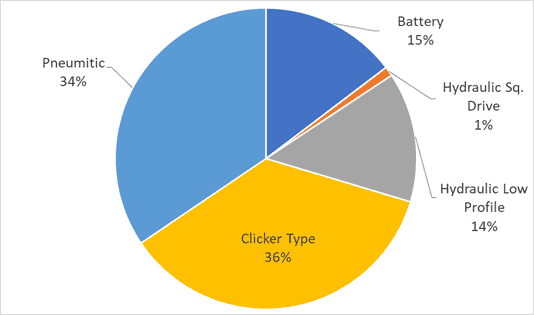
- 49% of all wrenches used were pistol grip tools. This was higher than what we expected.
- 36% were clicker wrenches. This was lower than what we expected.
- 14% were low-profile hydraulic wrenches. This was lower than we expected.
- 1% were hydraulic square drive wrenches. This was surprisingly lower than we expected.
The hypothesis going into the turnaround was that the clicker wrenches would be roughly 60%, while the pistol grip and hydraulic wrenches would split the remaining 40%. However, the data shows that the pistol grip wrenches alone consisted of 50% of the total use.
After discussions, we determined that there was plenty of battery and pneumatic torque wrenches, and the assemblers found them easier to use than clicker wrenches. This led to higher usage of pistol grip wrenches instead of clicker wrenches.
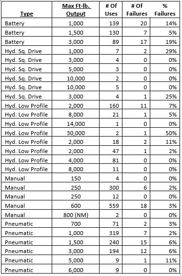
Amount of Failures Per Each Type of Wrench: Failure was determined if it did not meet +/-5% of the test fixture’s target torque associated with the tool. If the wrench failed one of the three settings, it was considered a failure and re-calibrated.
The above table shows the % of failure per wrench Model and the tool model type. Some tools had less than ten uses, so they should be ignored as, statistically, we don’t have enough data to determine if the failure rate is accurate.
Note: Hydraulic Square Drive tool data is omitted as none of the sizes qualify for 10+ times of use.
Percent Failure Rate Per Type of Wrench
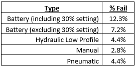
The above table shows that the wrenches did not meet the +/-5% criteria; however, most failures were within +/-10% of our criteria. We found only one tool that was grossly out of calibration.
After further reviewing the battery data, we found that most of the failure rate occurred on the 30% setting. If we removed the 30% setting test from the failure data, the failure rate would be 7.2%.
In other testings, the accuracy of powered equipment has inherent inaccuracies when set to <20% of torque output. This is why the lowest test settings we conducted were at 30%. However, failure rates that occurred at 30% were only 2-5% off our target +/-5%. This data reinforces that the Powered Equipment’s final passes should be 30-90% of the torque wrenches output.
Torque Verification Recommendations
Hex Technology and the refinery have noticed that “torque verifiers” would suffice as a substitute to a complete re-calibration of the tools. The Torque verifiers we used for square drive tools can handle up to 5,000 ft/lbs of torque. 85% of the tools used in this turnaround could undergo torque verification.
The NORBAR TruCheck that we have mentioned earlier is great for this kind of torque verification. This device was used in the turnaround to verify that the wrench is accurate and to remind the assembler that this is a precision instrument and to use it correctly.
Smart Sockets can also be used to verify the accuracy of torque with powered equipment on the flange.
Conclusion
It has been noted from previous research that manufacturers do not supply calibration specifications for their Powered Equipment Torque Wrenches, and there is not an industry standard for calibration of these wrenches. This is not good for the bolting industry as it can cause discrepancies in the target torque that translates to bolt/gasket stress that End Users require.
It should also be noted that there is no method of determining the frequency of re-calibration as roughly 5% of all wrenches will be out of calibration during a turnaround, which we would consider moderate usage.
It is good practice to incorporate torque verification tools to ensure that you are using properly calibrated equipment.
Until the industry standardizes on a calibration verification method, End Users can use the tools to assess/audit their suppliers to see if their accuracy and calibration method are sufficient to meet its requirements. We have found that any method of calibration or verification should be compared with the flange setup that has been written about in previous papers.
ACKNOWLEDGEMENTS
We want to thank the following companies for assistance in this paper:
RAD Torque Systems for support with torque verification methods and tools.
Torque Tools Inc. for support gathering this data.
C&S Technology for helping put this idea together and collecting the initial data.
References
Importance of Calibration (2011): “The analysis of data performed for this paper has also demonstrated the usefulness of the calibration procedure in detecting wrenches that should be repaired or replaced. For the manual and hydraulic wrenches studied, several had test results after calibration in excess of 10% above or below the target torque.” [2]
Justification for one standard of calibration (2012): “There are many misconceptions within the industry of when, how, why, by what standards, in what time-frame and by what definition calibration should occur.” [3]
Is there a difference in practical application on performance of Powered Equipment vs. the manufacturers claim for accuracy and repeatability (2017): “None of the tested equipment met its manufacturer’s accuracy claim and only Tool A pneumatic used on the NPS 8 flange met the manufacturer’s repeatability claim. Of the two twin tool sets tested, both sets showed a 7-10% difference in accuracy between twin tools.” [4]
Reinforcement of calibration verification method of using actual flanges for verification process (2018): “Powered torque wrenches (hydraulic and pneumatic) all trended approximately 5% to 30% low on final bolt load. This agrees with the results of last year’s testing presented in PVP2017-65800 “Determining Accuracy and Repeatability of Torque through Powered Equipment” but brings up the question of why powered tools have consistently provided low bolts loads in two separate studies.” [5]
It was confirmed that manufacturers can adjust their calibration methods to achieve better accuracy on actual flanges instead of transducers (2019): This work, along with the studies of the past two years, has provided a workable method to validate calibration of powered equipment through performance testing. In our case, the process of checking the tool’s performance on four different size/pressure rating flanges and checking bolt stresses with a bolt load gage as an indicator provided a good indication of each tool’s performance.” [6]