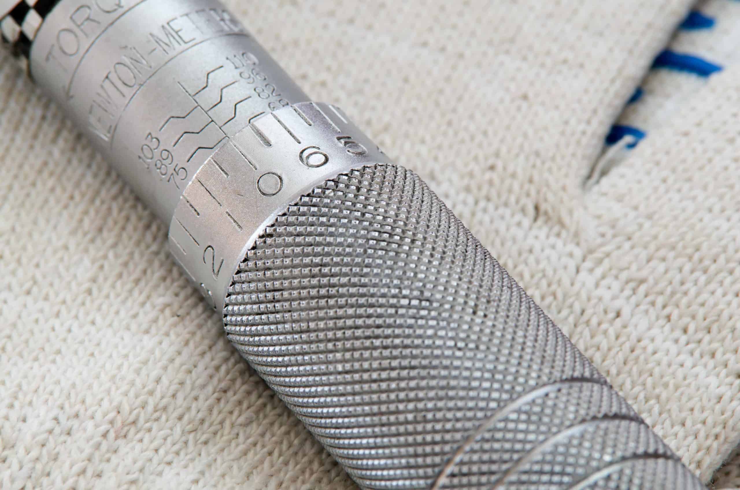
In 2005 I started selling hydraulic torque wrenches. Like many young salesmen, I instantly thought I was a “Bolted Flange Joint Expert.”
(Today I consider myself a recovering Bolting Expert.)
When customers asked about how flanged joints worked, my go-to response was, “well, target torque is the only thing that matters.” I didn’t consider things we now know are essential, like…
- assembly procedure
- tightening sequence
- the guidelines in ASME PCC-1
I just looked at bolt stress (really, the percent yield of the stud), and a little bit on the “cross pattern” (a.k.a. the star pattern), but that was it. If you gave me a torque value or bolt load, I wouldn’t necessarily know why or how it was generated. I just knew how to apply the tightening method to the appropriate fastener size.
What “Bolting Experts” Often Miss (or Misunderstand)
It’s a problem that still occurs today. Despite being one of the oldest assembly practices in industry, bolting techniques are often learned on-the-job, delivered from seasoned assemblers to greener staff. While this may cover some of the basics, word-of-mouth training often fails to address fundamental concepts such as…
- ASME B31.3
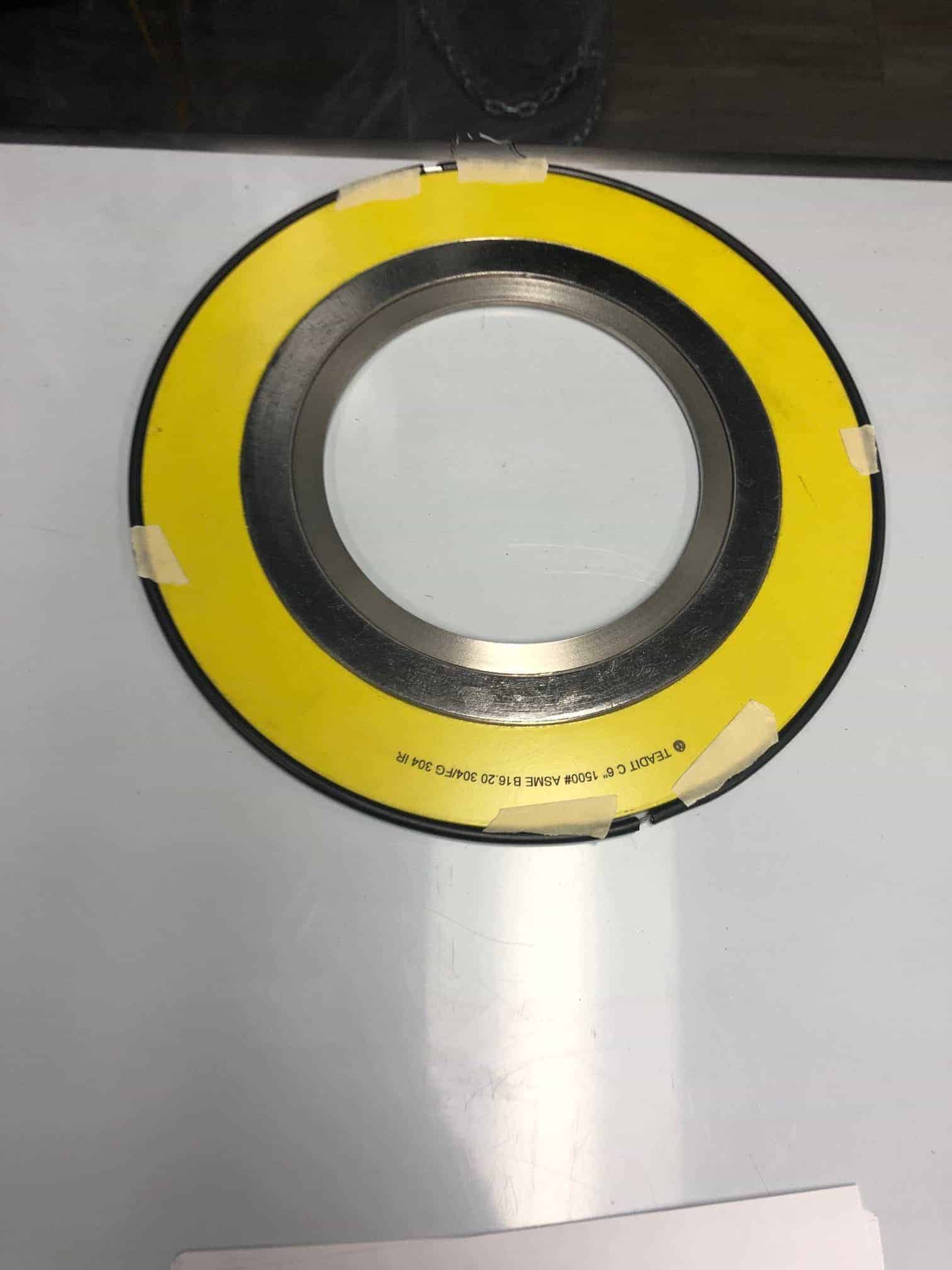
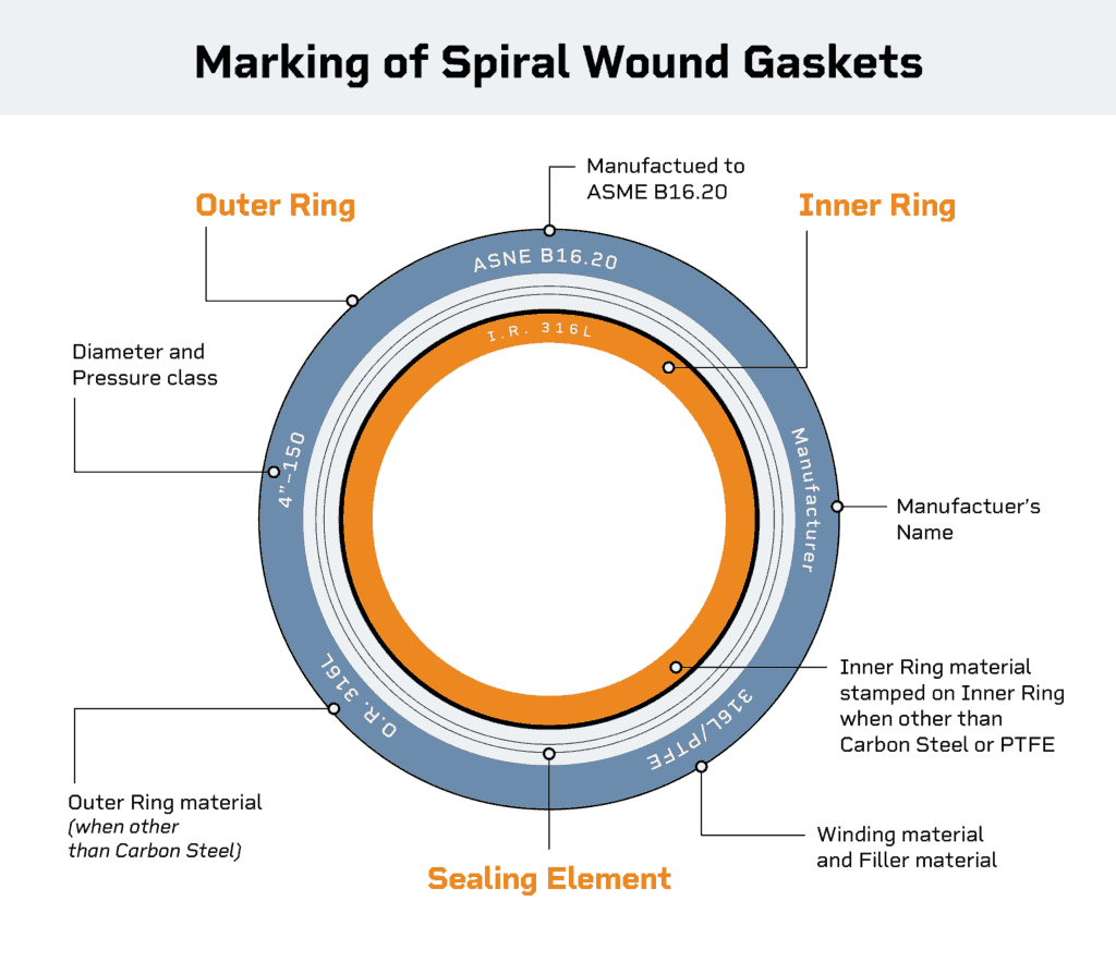
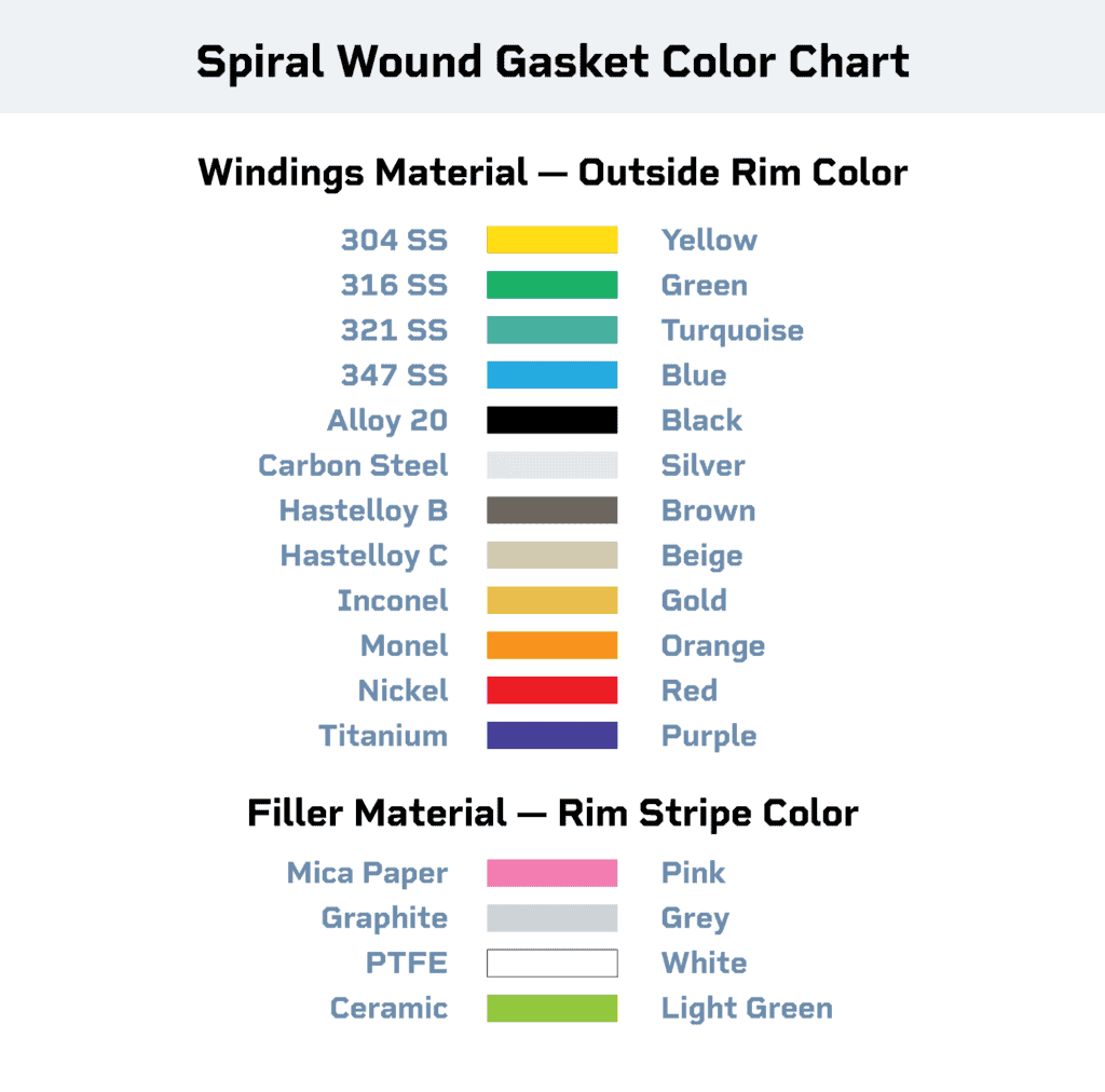
- how spiral wound gaskets work
- how ring-type gaskets work
- how pressure vessels work
- proper bolt lubrication practices
- what good joint integrity looks like
And really, that’s just the beginning. The field of bolted flange joint assembly goes far deeper. More than 15 years later I’m still learning new things about bolted flange joint assembly (BFJA).
Often, I get asked a question that was on my own mind back at the beginning: “Where can I go to learn about BFJAs (both pipe flanges and heat exchangers)?”
Best Resources for Understanding Bolted Flange Joint Assembly
There are good authors and publications, and bad ones, within bolting. I’m not going to waste your time by listing resources that aren’t worth reading. Instead, I’ve collected materials about the past, present and future of the bolting industry you ought to know. However, this list is always growing so don’t just stop here!
(NOTE: These books are for references to concepts. They aren’t a recipe for the assembly of BFJA’s or proper flange assembly practices.)
The Classics: John Bickford is the first author of BFJA books. Some of the material is outdated now, but they still are good reference material. He has three and the below listing is in order and not rank with a description of each book. They are not cheap ($200+ each) and you can find them both on Amazon:
- An Introduction to the Behavior of Bolted Joints – This is the first book he published. It’s my second-favorite of his works because it talks about basics but the book that followed it (listed below) has a better scope of concepts.
- Handbook of Bolts and Bolted Joints – Bickford takes his best articles from his first book and adds about 30 more articles from what were then “trusted resources” within the industry. Some of the articles are a little biased since they were written by the manufacturers of the products, but it will give you a good idea of how each topic functions.
The Present: The American Society of Mechanical Engineers (ASME) has published PCC-1 (Post Construction Committee -1) which is titled, “Guidelines for Pressure Boundary Bolted Flange Joint Assembly.”
This is the industry standard on how to assemble BFJA’s and is great for calculating gasket stress, K-Factors, training, etc. One should be very familiar with this document and is a good jumping point for a holistic understanding of bolted flange joints.
You should also read “Welding Research Council Bulletin 538” which has the background on many topics in ASME PCC-1.
For Upstream Applications, you should also read through API 6A.
Also for the Present: My new favorite book that has been updated frequently is published by Jose Veiga and it is titled “Industrial Gaskets.” You can download it for free at that link.
The Future: The American Society of Mechanical Engineers has an annual conference where BFJA’s receive their own section. You can find the research being done here.
Refine the search to “Bolted Flange Joints,” then narrow down by author. I highly recommend Dr. Warren Brown, who was my engineering mentor and is widely regarded as the foremost expert in the world on bolted joints today. However, you can filter by your topic and author on whatever you might be looking for.
NOTE: These articles normally cost $25 each.
Conclusion: BFJA Essentials
Today there are still many people in the BFJA industry who claim to be “experts.” Most are…on own products. But many of these individuals don’t possess a holistic understanding of all the parts that go into proper bolted flange joint assembly.
After many years of reading through the work of these experts and their opinions, I’ve found that sticking to the basics is the best path. Therefore, my recommendation is to follow ASME PCC-1 guidelines as the standard and use the different references to understand the items in ASME PCC-1. (Find more on ASME PCC-1 Training, and how to use it in your organization, here.)
When you research these topics, please remember: Keep it simple. Also, beware if someone tells you any of the following:
- “We have had 100% success…” (<-No, no you didn’t.)
- “This product brings together the best from X product and Y product…” (<-If it brought together only the “good,” where did the “bad” go?)
Also remember: You can’t out-procedure a lack of training. ASME PCC-1 Appendix A discusses the joint assembly procedures that all bolted joint assembly personnel should know, and serves a good syllabus for all individuals associated with BFJA’s to understand.
RELATED: Read our guide to clicker-type wrenches.
Join Industry Leaders!
Subscribe to Hex Technology today and we’ll give you $700 in bolting courses, FREE. Your path to a safer, more reliable, more profitable site starts here.