Bolt Tensioning Guide: Uses, Safety and Troubleshooting

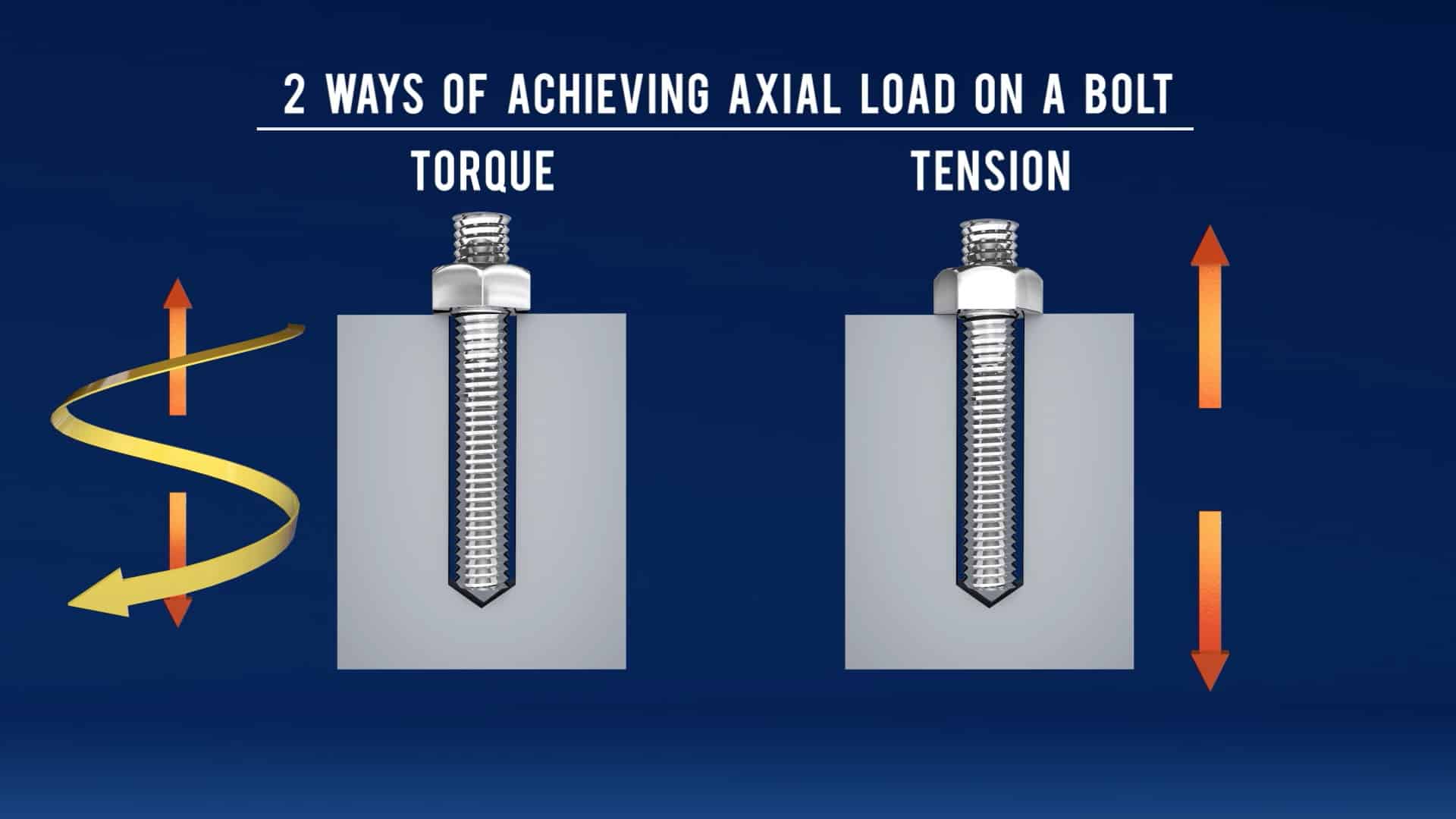
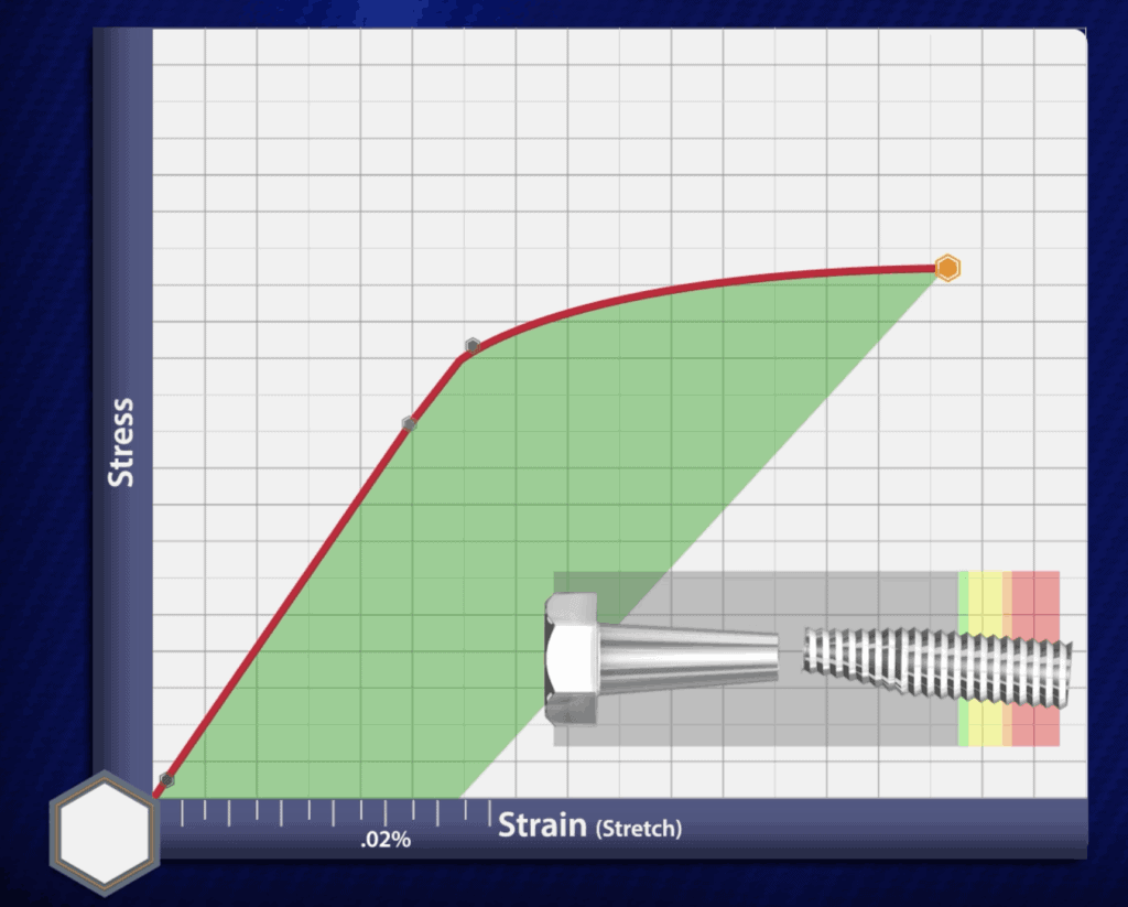
Bolt Tensioning: An Overview

Hydraulic bolt tensioners more commonly used for bolting applications in Europe than the United States. You’ll typically see hydraulic tensioning used on fasteners with 2″ bolt diameter or greater, but they can operate on studs as small as ¾” bolt diameter

Tensioners are common in subsea (both topside and underwater), wind turbine, and power generation applications, but are less frequently used in the oil & gas industry. Within the oil & gas industry, however, a good use of tensioning tools is on fasteners in critical bolted joints such as heat exchangers and other large pressure vessels

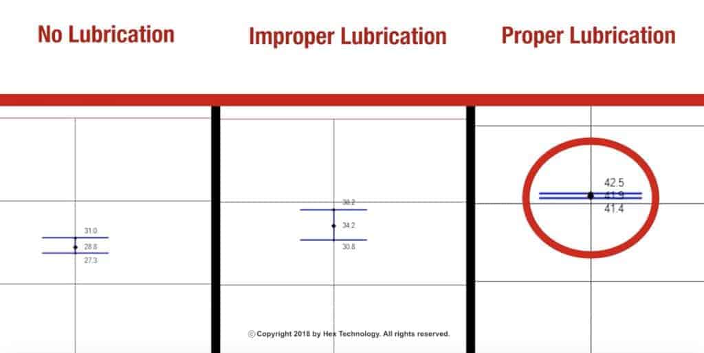
When you use 50% or greater tensioner coverage, you can achieve more even and accurate gasket compression than when you use one (or even 4) torque wrenches.  

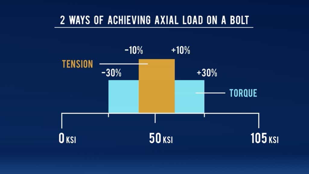
One of the main advantages of stud tensioners is that they eliminate the friction factor (or k-factor) on the stud and nut face. In fact, tensioners are more accurate in general, achieving a plus-or-minus 10% accuracy rating compared to 30%

Accuracy of bolt tensioning vs torquing, compared.

It is typically stated that you can also reuse stud bolts more frequently when you’re using hydraulic bolt tensioners, since you don’t have to worry about galling or any frictional forces on the fastener. While this is true in laboratory applications, be aware that in the field, you have to take into account operating conditions like temperature and pressure, which will affect the fasteners over time. 

Using Bolt Tensioners in the Field

One limitation of tensioners is the need for greater spacing. While this typically isn’t an issue on normal piping flanges, you might not have enough space for a tensioner on valves and other custom flanges like you’ll see on heat exchangers

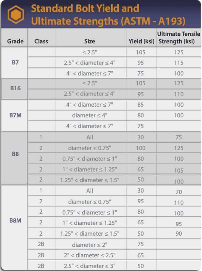
Also, the maximum fastener stress that tensioners can achieve is normally around 50,000-60,000 psi of stud preload. If you plan on tensioning to more than 60,000 psi, you’re probably going to need a specialty tensioner

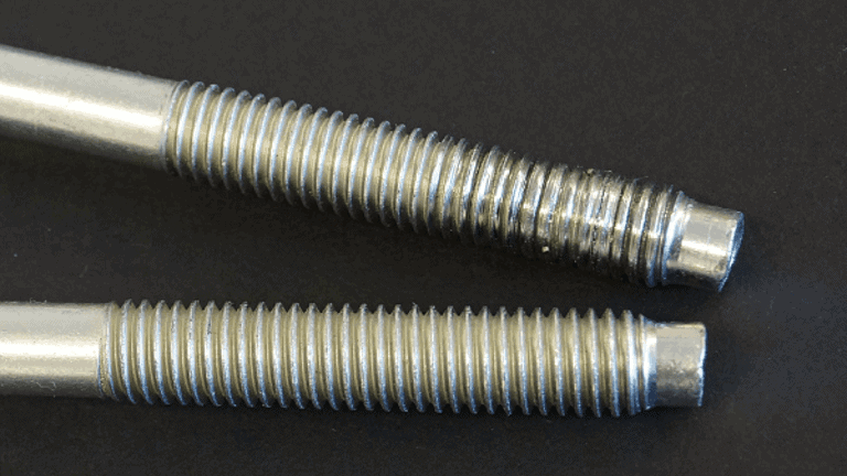
You also need additional stud length for tensioning. The rule is you need one diameter of the stud sticking above the nut so that the puller bar can grip the stud when the load cell presses on it. Therefore, to calculate the proper size, you take the normal stud length you would use for torquing and add on another diameter of that stud to it. 

Do not use washers with tensioners. The footprint of a tensioner can sit on the washer, bow it up, and the tensioner gets locked on as a result.

Another disadvantage of tensioners is they don’t do well in elevated temperatures. What does that mean? Well, the startup re-torques you might ordinarily do are fine with torque wrenches, but tensioners can’t be used that way because the seals will blow and won’t hold the pressure. So with tensioning, you can assemble the flange at ambient temperatures just fine, but after startup you can’t go back and do what some people call a “hot tension pass”.

NOTE: There are other bolting tensioning tools such as hydraulic nuts that we do not discuss in this article. 

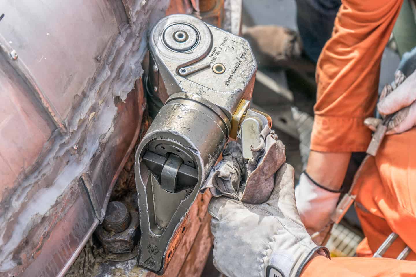
How Hydraulic Tensioning Works

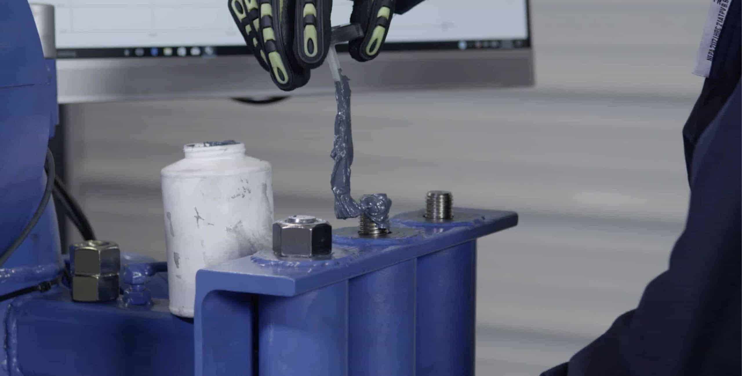
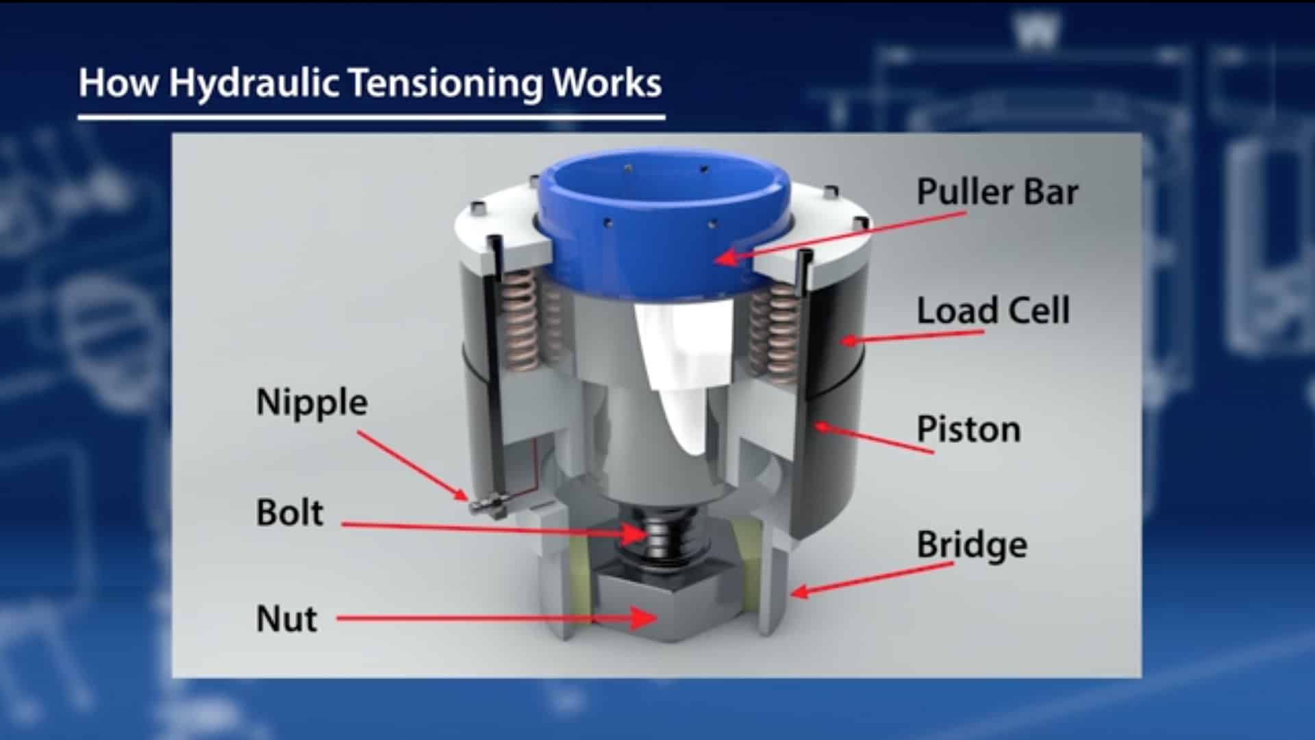
Starting from the bottom of the unit, the basic parts of a hydraulic tensioner are:

Nut: This sits on the flange, while the bridge sits around the nut. As you can see, the bolt protrudes through the nut, and you need to make sure that you have one diameter of that stud sticking above the nut. 

Load cell: This sits above the nut, and has the hydraulic piston inside of it. Attached to the load cell is a nipple for oil to come in at a designated hydraulic pressure from the tensioner pump

Puller bar: This sits on the piston, which is threaded onto the stud. The hydraulic pressure in the pump and the diameter of the load cell determines how much force you’ll exert on the bolt.

Bolt tensioning on 50% and 25% of bolts within a flange.

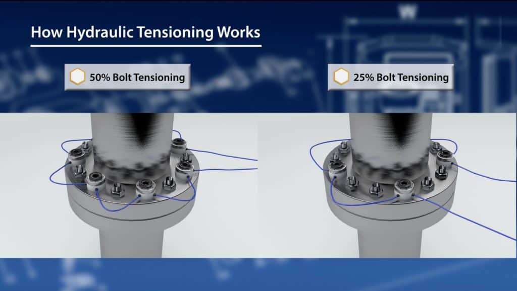
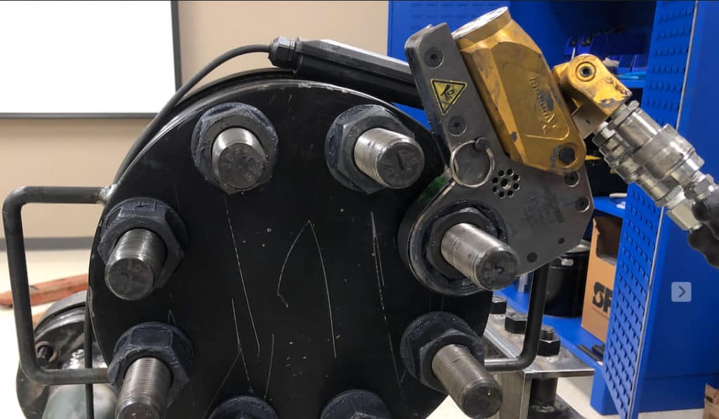
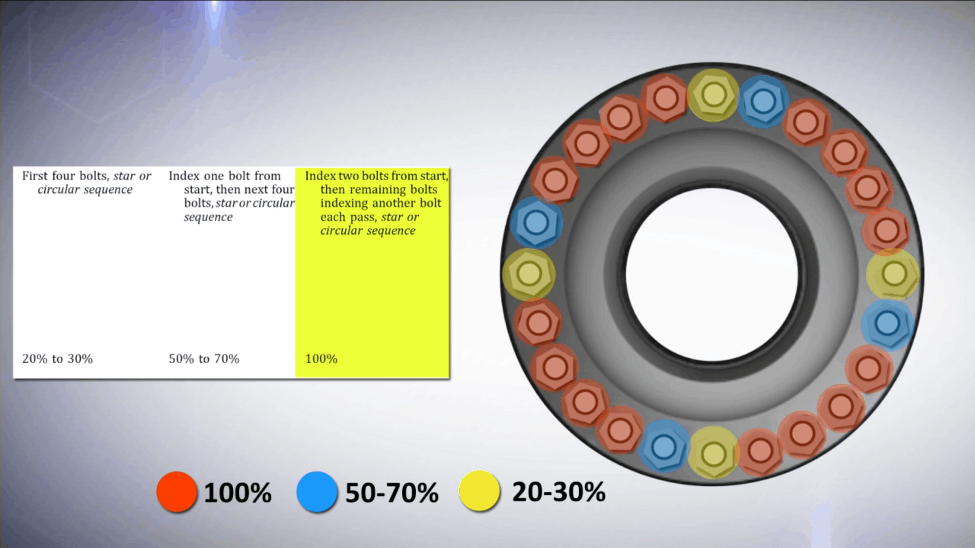
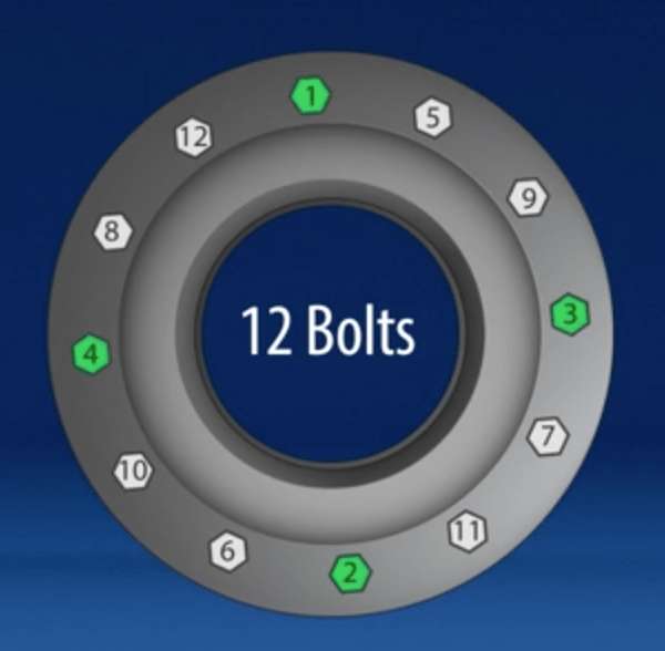
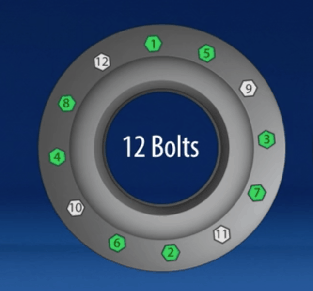
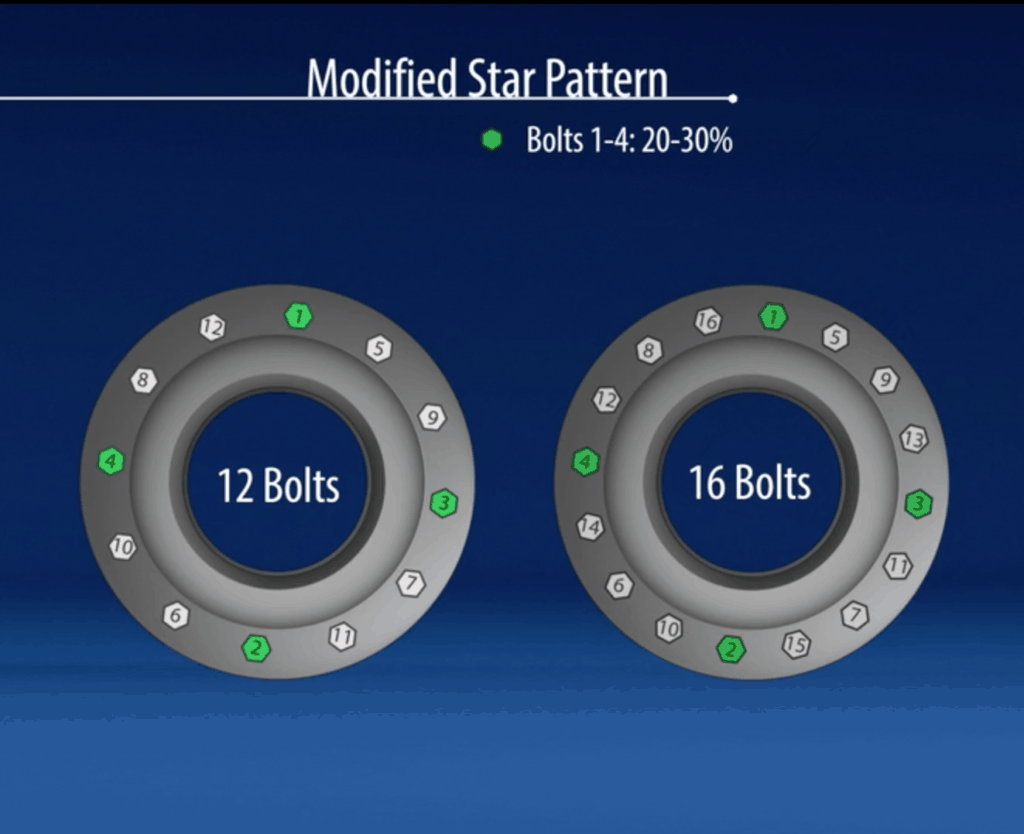
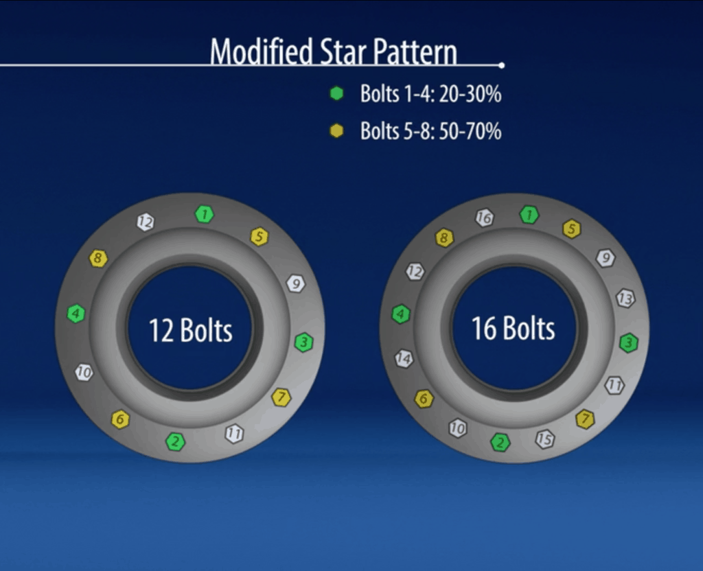
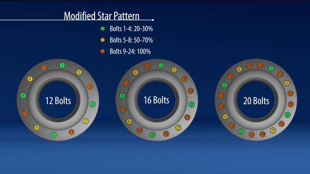
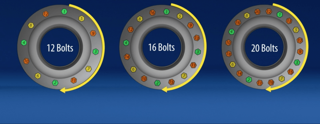
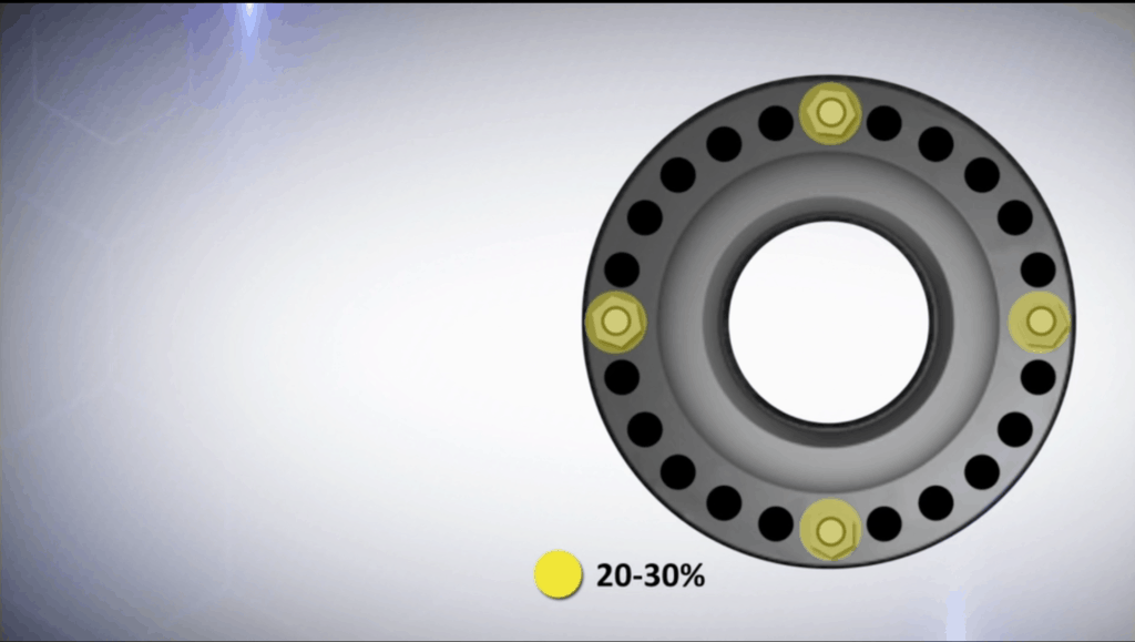
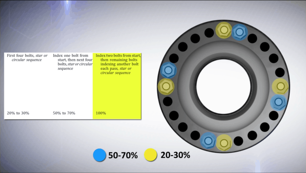
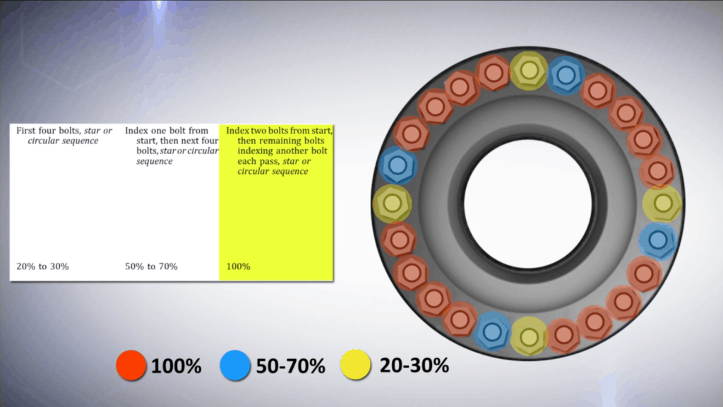
50% coverage (shown above, left), or one tensioner on every other bolt, is standard. While it’s possible to do 25% coverage (above, right), we don’t recommend this approach because it requires more passes, is harder for the assembler to execute, and your accuracy starts going down. Therefore, when you have 50% coverage, you’re going to have what we call an A pass and a B pass.

BOLT TENSIONING EXAMPLE: Let’s say your target is 50,000 psi bolt stress. First you need to consult with the tensioner and the engineer to make sure you have all your load loss factors figured out. But for this example, you’re going to tension your A pass 20% above what you would do your B pass. Your B pass is your final bolt load. But because we’re only putting load on half the bolts and we’re trying to bring this pipe together and compress the gasket and everything else, we actually kind of have to go over what our target is so that when we bring our B pass in, the load transfer is going to happen and it should equalize out. Now a common practice is to go back to your A’s and just double check that you still have the correct bolt load on there and do your B pass on your A’s.

Hydraulic Tensioning Safety

Safety around hydraulic tensioning is absolutely important. Your primary concern is that you are working with high pressure hydraulic fluid, which goes from the tensioner pump to the load cell and then on to the other tensioners. A high-pressure fluid can cause massive injury, so always ensure that proper storage, cleanliness, and safety measures are taken prior to use. If you see a worn or damaged hose or fitting, please replace it. 

Additionally, your assemblers don’t want to be looking down at the tensioner while it’s in use, because if it pops off because of insufficient thread engagement, stripping, or anything else, it ends up being a bullet. So you always want to make sure you’re on the side of the tensioners, and not looking straight down at the puller bar.

Learn more safety considerations for all hydraulic equipment. 

Maintenance, Troubleshooting, and Calibration

Seals are the most common culprit for issues with a hydraulic tensioner. Just like with hydraulic torque wrench pumps, if you have oil, dirt, or any other gunk running through the hydraulic fluid, those impurities will get into the tools and eat away at the seals, which are then the first things to go. 

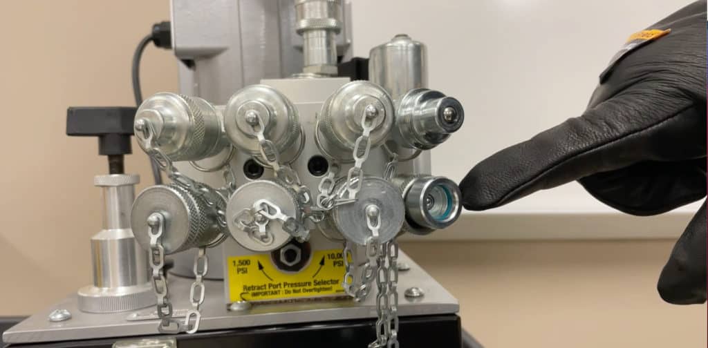
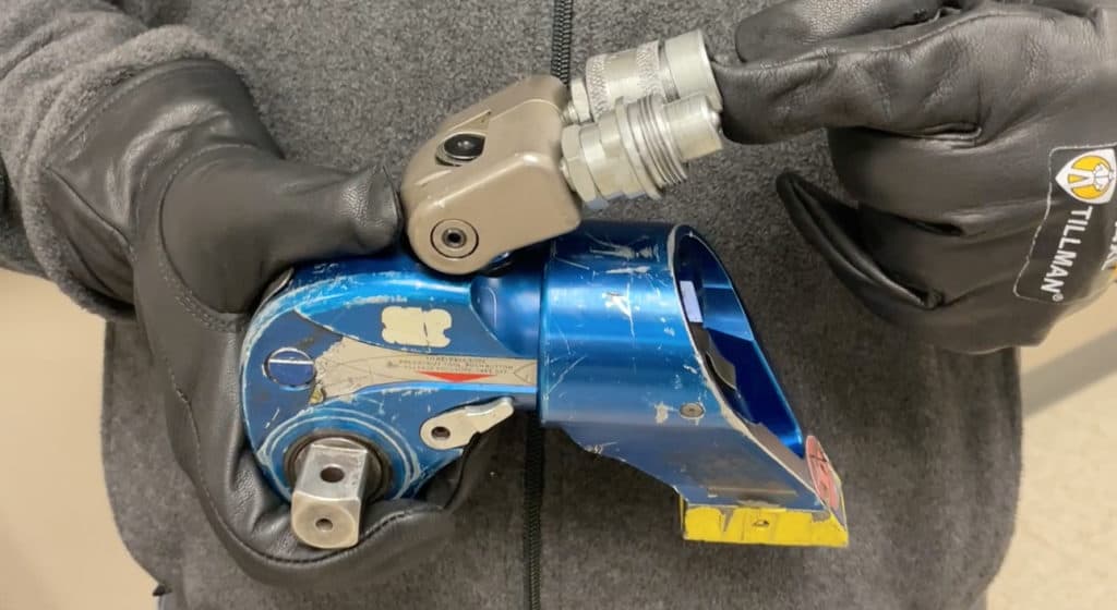
Outside of the seals, hydraulic tensioners don’t require a ton of maintenance. The only other big troubleshooting tip is if you’ve got a tensioner that is not working, you need to check your couplers. 

For calibration, all you’ve got to do is make sure the gauge was calibrated within the past 12 months.

Well-trained assemblers produce far more accurate results. Learn how a U.S. refinery achieved more consistent flange makeup.  

Join Industry Leaders!

Subscribe to Hex Technology today and we’ll give you $700 in bolting courses, FREE. Your path to a safer, more reliable, more profitable site starts here.

  • This field is for validation purposes and should be left unchanged.

Hydraulic Torque Wrench Use in Industrial Bolting

Hydraulic torque wrenches are a staple in the fastening of industrial bolting applications.

These wrenches are necessary to achieve high torque outputs (greater than 600 ft. lbs.) on a fastener. Manual clicker wrenches capable of reaching 1000 ft. lbs. do exist, but they are brutally difficult to use. Power tools are easier on the assembler and lead to better accuracy and repeatability.

Since hydraulic tools have a high torque output, they need to be powered by a hydraulic pump. This pump or “power pack” relays high-pressure hydraulic force through a hydraulic hose in order to produce the target torque output.

If calibrated correctly, the hydraulic pump will allow the user to change the torque setting accurately. Hydraulic pumps can be powered by either pneumatic (air-driven) or electric power.

Hydraulic torque tools can have a minimum torque of 100 ft. lbs. and a maximum torque of 120,000 ft. lbs.  Both the minimum and maximum torque depend on the capacity and size of the hydraulic equipment. Hydraulic torque wrenches are especially useful on large bolts (1-inch diameter or greater). In the sections below, we’ll explain how hydraulic torque wrenches work, starting with the pumps that power them and working outward to the tools themselves.

Hydraulic Pump (Or “Power Pack”): Where it Begins

A standard pump can generate up to 10,000 PSI, and allow you to adjust the torque setting on the hydraulic wrench. Most pumps work with all major tool brands.

Pumps are either electric or air-driven, though you’ll typically see pneumatic hydraulic pumps used in hydrocarbon processing. Using an electric pump for some bolting applications may require you to get a “Hot Work Permit,” due to the electricity.

For all hydraulic torque wrenches, a hose connects the hydraulic pump to the hydraulic wrench itself. The hose connections (or couplers) are set up so that you cannot hook up the hose incorrectly — the male/female attachments require the right match in order to connect (see photo above). Therefore, connecting the hose to the pump is intuitive and easy.

Hydraulic Hose: Keep an Eye on This Connection


After you power up the pump, you’ll adjust the pressure to match the correlated target torque value on the calibration sheet. The hose attached to the hydraulic tool on what is called the uni-swivel. Logically, the uni-swivel can handle up to 10,000 PSI.

IMPORTANT NOTE: Hydraulic hoses SHALL (i.e. must) be rated for a 4:1 hydraulic pressure, which means rated for 40,000 psi.

There are setting to advance or retract. Advance will fill the piston with hydraulic fluid, which then advances the piston to push on the drive pawls. The drive pawls rotate, which causes the nut to rotate.

ANOTHER IMPORTANT NOTE: Carefully inspect a hydraulic hose for damage or holes before use. If pressurized liquid were to escape through a hole, the stream that would result would be capable of causing severe injury (think: lost fingers or deep cuts).

Square Drive Bolting Tools: Best for Breakouts

The square drive bolting tool is the most common hydraulic torque wrench in industrial bolting. Square drive sizes include ½”, ¾ “, 1″, 1 ½”, 2 ½”. Size dictates the maximum torque output that these tools can generate.

Experience shows square drives are best suited for breaking out, as square drives are more robust and have fewer moving parts than low profile wrenches, making them less prone to breakage.

A square drive tool’s reaction arm places it further away from the flange (due to the impact socket and square drive), therefore square drives are more difficult to use for assembly than a low profile hydraulic torque wrench.

Low Profile Bolting Tools: An Assembler Favorite

Low profile hydraulic wrenches consist of two parts: A powerhead and a link. The link makes low profiles unique because each set of links fit over a specific size of nut. You can change the link by pulling the link pin, then sticking on a differently sized link.

Low profile wrenches go upward from 2,000 ft. lbs. to 4000, 8000, 16,000, and so on. You need a link for every wrench of that size, meaning you might need multiple links for a 2,000 ft. lb. version, multiple links for the 4,000 ft. lb. version, and so on. Links for different model tools are not interchangeable.

As you might guess from the name, Low Profiles are absolutely awesome when dealing with low clearance issues. The reaction point for a low profile is right up against the next adjacent nut. The low-profile wrench may be the assembler’s favorite hydraulic tool because it is easier to use than a square drive.

Hydraulic Torque Wrench Safety

With the high-pressure fluid and extremely powerful mechanical reaction arms, there is great potential for injury with improper hydraulic equipment wrench use. Hex Technology recommends any site that uses hydraulic tools first undergo safe use and operation training.

Always depressurize the hydraulic hose prior to use. Store hydraulic hoses in a circle wrapped end to end, and do not screw the ends on one side together. As mentioned above, if you see any steel braiding bins, cracks, burns or kinks, do not use that hose.

The other major safety concern for all hydraulic torque wrenches is pinch points resulting from reaction points. You know enough physics to know that for every action, there is an equal and opposite reaction. In bolting, this means that if an assembler is applying 1000 ft. lbs. to a bolt, the reaction arm is applying that same amount of force to the adjacent nut. You do not want any part of your body caught between those two pieces of metal.

There are two major types of hydraulic tool designs out there: Those with holding pawls and those without holding pawls. A holding pawl allows the tool to ratchet without using the “wind up” on the fastener. The holding pawl will get bound up on the fastener at some point, and while the tool will ratchet, it will be hard to take off the flange.

When this happens: DO NOT take a hammer to the tool. Instead, power up the tool through the hydraulic pump then depress the holding pawl, and the hydraulic tool will release.

Hydraulic Torque Wrench Maintenance

An important aspect of hydraulic torque wrenches maintenance are watching the seals. Often, these seals are the first thing to break. If you see oil in your hydraulic pump that looks milky, full of water, dirt, or grime, those impurities will travel along with the hydraulic fluid through your tool and eat away at your seals.

The second maintenance factor to mind are the hydraulic hoses. The couplers on hoses regularly get grime and gunk and everything else put through and onto them. Then people will place channel locks or pipe wrenches onto the couplers to try and tighten them. Please clean the fittings with each use so you don’t have to do this, as channel locks will damage and eventually ruin the couplers.

If you have to replace a fitting, please make sure to follow the hydraulic hose manufacturer’s requirements.

The hydraulic pump doesn’t usually require in-field maintenance, but may require some troubleshooting. Air-driven hydraulic pumps will have an FLR, or “filter lubricator regulator.” When you hook up air to your hydraulic pump, there’s a little nozzle on the bottom of the filter. Dump all the water and gunk and grime out before you start running your tool. Because if that gunk and grime go through your FLR, it will travel through the hose into your air motor, and tear up the motor.

You’ll see the FLR has a little sight glass that allows you to see the oil going in. Make sure the oiler is putting in one drip of oil every 10 seconds.  This oil lubricates the air motor, ensuring it doesn’t bind. Having the oil drip more frequently will lead to oil exhaust on the handle, but if the tool doesn’t oil frequently enough, it will bind up the pump and you’ll eventually have to swap the pump out.

It is our recommendation that you reach out to the torque wrench manufacturer. They normally do a safe use and operation and troubleshooting course on their tools, as each different manufacturing and each different model of tool has its own quirks and purposes for each individual part.

After any maintenance on a hydraulic torque wrench, you have to recalibrate the tool. It’s necessary to re-grease both the drive pawls and the side plates so the pawl can move back-and-forth easily against the side plate, doesn’t get bound up, and doesn’t gall.

Calibration: When and what’s required

There are two elements of a hydraulic torque wrench that need to be calibrated:

  1. The actual wrench itself.
  2. The gauge on the hydraulic pump.

Both of these components should be calibrated at least once every 12 months. Once the tool is calibrated, a new torque chart needs to be generated. The updated chart is what your crews will need to use with that tool from that point on. Always check the serial number and date to ensure you have the correct calibration chart for that tool.

If you have questions or your site needs training on the use of hydraulic torque wrenches, contact Hex Technology.

Join Industry Leaders!

Subscribe to Hex Technology today and we’ll give you $700 in bolting courses, FREE. Your path to a safer, more reliable, more profitable site starts here.

  • This field is for validation purposes and should be left unchanged.

Bolting Applications with Pistol Grip Torque Wrenches

Roughly 25 years ago, pneumatic torque wrenches (a.k.a. pneumatic torque gun or pistol grip) torque wrenches were commercialized enough to make them one of the main staples for bolting solutions found in oil & gas or power generation.  We have seen the pneumatic torque wrench technology move to both battery and electric powered pistol grip torque wrenches to improve the accuracy and repeatability in bolting applications.  

The oil & gas bolting industry has seen an increase in pistol grip tools as they are ergonomic, heavy duty, have an adequate torque range for most fasteners, and have high-speed continuous rotation without having to ratchet.  This makes them faster than other controlled torque options (such as hydraulic torque wrenches).

We typically see pistol grip wrenches in heavy duty applications because in order to achieve a high torque output (typically greater than 500 to 600 ft-lbs) on a fastener you should where it is easier on the assembler and you can generate better accuracy and repeatability than with an impact wrench or other unregulated “torque tools.”

Pistol Grip torque wrenches consist of a motor (typically powered by air pressure, battery power, or electricity), a gearbox design (planetary gearbox or gearbox) which acts as a torque multiplier,  a square drive, and a standard reaction arm

  • NOTE: These pneumatic tools should not be confused with impact wrenches as impact wrenches do not have an FRL (filter-regulator-lubricator) or another regulated power source (electricity or battery power).
  • Since these pistol grip wrenches have a high torque output typically ranging from 50 ft-lbs to 15,000 ft-lbs. Both the min and max torque range is dependent on the capacity and of the square drive size. Each one of these pistol grip torque tools has a calibration certificate specifically for each tool (serial number and not model) that has the readout of the input vs. the torque value (typically found in ft-lbs or Newton-Meters).  

NOTE: Hex Technology has had significant experience with pistol grip torque wrenches and suggests contacting us if you have further questions after this article.

NOTE: See our articles on Hydraulic Torque Wrenches and Stud Tensioners for other power tool options to achieve high loads on fasteners. 

Pneumatic Pistol Grip Torque Wrenches

The first type of pistol grip torque wrenches that we will discuss is the pneumatic torque wrench. These are powered by air pressure that goes through the air motor, and at the end of the gearbox is a reaction arm that is used to absorb the torque and allows the tool operator to use it with little effort (thus making it ergonomic). These guys are great because they have a very high torque output and they’re normally smaller than an impact wrench as well. 

These advantages include being relatively easy to use. If you’ve used an impact wrench, the only difference with a pneumatic torque wrench is that you’ve got to do is dial your torque with the FRL Some of the best reasons to use pneumatic torque wrenches is they have no vibration, operate at less than 80 decibels, are ergonomic, and they have a higher torque output than what impact wrenches do.  

NOTE: All pneumatic tools are not the same. An impact wrench does not have accuracy or repeatability while pneumatic torque wrenches do. 

Battery-Powered Pistol Grip Torque Wrenches Work

Battery-powered pistol grip tools are more common in the oil & gas industry now than they were 10 years ago, and I project that they’re going to be even more common than pneumatics in the next couple of years because it was just so convenient to use.  

Since they are battery-powered, you do not need an air hose or electrical socket!  They are typically more accurate and repeatable as they have a digital gauge and not a dial gauge.

Electric Powered Pistol Grip Torque Wrenches

The pistol grip wrench that we’re going to talk about is electronic torque wrenches. We don’t see these a lot in the oil & gas industry because it needs electricity, which means you need a hot work permit. We see them more in the power industry, wind industry or structural steel industry, but you can see right here that it’s got an entire box dedicated to setting the torque value and then there’s an output to the wrench itself. Each manufacturer has got strict calibration requirements for these, so please contact them if you’ve got any questions. Do not go into that box and try to adjust it yourself, as that will be a very expensive mistake.

Pistol Grip Torque Wrench Safety

The first thing we’re going to talk about when using these wrenches is safe use and operation. Pinch points are a common safety hazard around the reaction arm of these tools. The reaction arm swings over and reacts against the next nut or possibly the flange. That is not a handle, do not use it as a handle. Keep your hand as far away from the reaction arm as possible. If the torque wrench is putting out a thousand foot-pounds, that reaction force on the reaction arm is going to be a thousand foot-pounds and you’re going to lose a finger.

It is also important that the user have a solid reaction point. Curved or bad reaction points can cause the tool to bind up and put excess load on the gears within the tool. Multiple reaction arms are available from the manufacturer to achieve proper reaction arm placement if the standard reaction arm is not suitable for your application. 

Pistol Grip Torque Wrench Maintenance 

When talking about the maintenance of these tools, you have to remember that they are precision instruments and should be treated that way. Don’t just leave them in the back of the truck overnight. Make sure that they are in an environmentally controlled place so that rain doesn’t get on them, water doesn’t get on them when they’re not in use.

Preventative maintenance will give early detection of worn-out tolerance in these tools and prevent premature failure. For pneumatics, one of the things that we like to do is make sure that when you plug the air in on the FRL, there’s a little nozzle on the filter that you can loosen and it spits out all of the water and all of the dirt that you’ve gotten inside of the hose. Also, make sure that your lubricator is filled with air tool oil. You can see one drip every 10 to 15 seconds from the sight glass of the lubricator.

Unfortunately with the electric and the battery-powered, there’s not a lot of preventative maintenance that you can do on these tools as everything is pretty much closed circuit. The one thing I do not want you to do is go in and try to fix that planetary gear set yourself. It is super complicated with hundreds of moving parts, and you’ll probably end up buying a new tool if you do that. 

Also if you hear anything not working properly, it’s making a grinding noise, don’t keep pulling the trigger because that’s $500 a piece, and get it to a licensed repair shop to get fixed and recalibrated.

Pistol Grip Torque Wrench Calibration Certificate

Calibration certificates for all of the pistol grip wrenches are pretty much the same, and while there is no industry requirement, the standard is to calibrate these once a year. However, these tools should be load verified throughout that calibration year. Meaning you should put them on a Skidmore (or equivalent) and test their accuracy and repeatability just to make sure that the tool is staying within its calibration certificate‘s torque readout.

Conclusion

In conclusion, pistol grip torque wrenches are absolutely awesome to use in the field as they’re super convenient and are high speed (because they do not have to ratchet) compared with other bolting torque methods. With the battery torque wrench, you don’t have to have a hose, you don’t have to have a box, so they’re really easy for the one off flanges. They will probably break down more frequently than the pneumatics just because the handle is not as robust. However, all these wrenches are great for piping flanges, heat exchangers, manhole covers, and any heavy duty bolting applications found in oil & gas

All pistol grips are square drive tools, so If you can fit an impact in there, you can fit one of these torque wrenches in there.

Join Industry Leaders!

Subscribe to Hex Technology today and we’ll give you $700 in bolting courses, FREE. Your path to a safer, more reliable, more profitable site starts here.

  • This field is for validation purposes and should be left unchanged.

Bolt Tensioning vs. Torquing: Pros, Cons, and Accuracy

Correct Fastener Preload: What We’re Trying to Achieve

Before we dive into the comparison of bolt tensioning vs. torquing, let’s remind ourselves what we’re trying to achieve when we use either.

The ultimate goal in bolting is to achieve the correct fastener preload (also known as bolt load or axial load). Applied appropriately to a gasketed bolted connection, the bolt load creates clamping force (or “clamp load”) on the gasket. The result: A reliable, leak-free seal.

Bolt torque and bolt tensioning are both legitimate ways to seal a joint. Bolt torquing exerts a rotational force on the fastener, while bolt tensioning involves stretching a fastener with what looks like a hydraulic load cell.

Which is the “best method”?

Well, a torque wrench sales guy would tell you torquing is the way to go. A tensioner sales or service guy would tell you tensioning is the best way to do things. But really, which is “best” is a loaded question, and depends on…

  • Joint criticality
  • Joint component accessibility
  • Available equipment
  • Expertise of personnel

…and more.

In this article, we’ll provide definitions of for bolt torquing and bolt tensioning, explain some pro’s and con’s for each, and offer guidelines for the use of each.

NOTE: For the sake of everyone’s time, we’re not going to talk about tension indicators, hydraulic bolts, or direct tension indicating washers.

What is Bolt Torquing?

A clicker wrench applies torque to a bolt.

Torquing is the most commonly used way to achieve fastener preload with bolted joints. Torquing produces this load through rotational force on a nut or bolt head. This torque is usually measured in foot-pounds (ft-lbs.) or Newton-meters (Nm).

Whether the bolt torque is achieved through the use of a manual “clicker” torque wrench, pistol grip torque wrench, or a hydraulic torque wrench, it is the most simple method of achieving axial load.

The big advantage to torquing is that is typically more cost-effective than tensioning.

However, the skill levels and training of those who use the torque tools equipment are determinants of how successful and accurate torque tightening will be.

Additionally, to achieve correct torque-tension relationship, the K-factor is critical. (And note, K-factor is NOT the same thing as coefficient of friction.) A proper K-factor is critical for understanding what applied torque value you will need.

You also need to take into account friction on bearing surfaces, the bolt diameter, and other variables, which are best examined through experimentation.

What is Bolt Tensioning?

Bolt tensioning on 50% and 25% of bolts within a flange.

As mentioned above, bolt or stud tensioning produces axial load by pulling up on a fastener with what looks like a hydraulic load cell.

To achieve the targeted bolt load, you need to know the area of the tensioner and the amount of force on the fastener, and then adjust the amount of hydraulic pressure.

Hydraulic tensioning began in the 1970s, and in the 50+ years since, tensioning has become more common on specific applications, especially high-pressure flanges with large bolt diameters or critical joints across many industries, including oil and gas, wind, subsea, and power generation.

Because tensioning does not place a twisting force on the fastener as applied torque does, we see tensioners used with long threaded fasteners and on rotating equipment such as reciprocating rods.

Another good use of tensioning is large bolt diameters. On large bolt diameters, tensioning will save you time compared to using hydraulic torque wrenches.

Bolt Torquing vs. Tensioning: What’s More Accurate?

Accuracy of bolt tensioning vs torquing, compared.

Tensioning is more precise — but there are ways torquing can narrow the gap, if it’s applied correctly.

Torque tools are generally considered accurate within plus or minus 30%. That means if your target was 50 KSI of load, you could see anywhere between 35 KSI and 65 KSI bolt load on your fasteners, and you’d be okay with that.

(The differences in bolt load from fastener-to fastener in flange is known as “bolt scatter.” The lower the bolt scatter, the more consistent the flange assembly.)

With tensioning, you’re typically going to see +/- 10% accuracy. That means your bolt scatter will be lower. If the target was 50 KSI, you’d see values between 45-55 KSI.

However, there are some important caveats to note here.

First, tensioning is more expensive and more complicated than torquing. So you will need people who have been properly trained in order to properly apply stud tensioning. Torquing, on the other hand, is fairly simple and torque wrenches are readily available in any industrial plant.

Second, torquing can be significantly more accurate than 30% when performed by an appropriately trained assembler, with proper lubrication and with calculations that include a proper (experimentally determined) K-factor. It’s not uncommon for well-trained craft assemblers to achieve +/- 15% accuracy or better with torquing.

Related:

The Stud Guide: B7s, B16s and Other Common Bolts

Torque Calibration in the Lab and the Field

The Myth About Bolt Yield

Join Industry Leaders!

Subscribe to Hex Technology today and we’ll give you $700 in bolting courses, FREE. Your path to a safer, more reliable, more profitable site starts here.

  • This field is for validation purposes and should be left unchanged.

The Myth About Bolt Yield

Watch What Happens When You Take a Bolt Past Yield

Let’s start with the big myth about steel bolts and yield strength.

What we often hear from people in the field is: “Well, if the bolt is broken, it’s been put into yield.”

That’s not actually true.

The video below shows you what happens when a bolt goes past its yield point.

Note how you can’t tell there’s a problem with the threaded fastener just by looking. It’s easy to tighten the bolt past the yield point and not know you are past permanent deformation.

And notice how even after the steel bolt has surpassed minimum tensile strength, a nut will still run up and down the threads just fine.

What is Bolt Yield?

A bolt’s yield point is where the stress placed on a fastener surpasses its ability to recover its elasticity.

Remember: Steel may seem firm, but it’s actually an elastic material. That means when you fasten a bolt, you are actually stretching the material.

The stress applied to a bolt is known as “tensile stress” or “preload.” In the graph below, you’ll see stress graphed on the y-axis, while the amount of stretch on the fastener is shown on the x-axis.

Bolt Yield Stress vs. Strain Curve. Note how the relationship is linear up until the yield piont (.02%)

The preload added to the threaded fastener remains pretty linear — until you reach the yield point. This is known as the proof load or proof stress, and it’s the maximum load a fastener can take before it hits permanent deformation (also known as plastic deformation).

When a fastener reaches a point of plastic deformation, in simple terms, this means the fastener won’t go back to its original shape. (Technically, this means the bolt won’t go back to being within .02% of its original shape.)

If you were to continue applying load and stretching the fastener, the stress-strain curve takes a bad downward path:

Bolt Yield Stress vs. Strain Curve: Note how, past the yield point (.02%), the relationship is no longer linear and the curve heads downward.

If we keep stretching the fastener until we hit the ultimate tensile strength (also called maximum load). This is when a bolt starts “necking” and, eventually, breaks.

But long before the fastener breaks, since the curve past the yield point is not linear, we do not know the preload of the stud. Therefore can’t predict the clamping force the fastener is placing on the flange.

Once we understand this we can address the property classes of each common material found in the industrial industry.

NOTE: This article will concentrate on ASTM A193 & ASTM A320 type of fasteners. It does not address metric bolts, SAE J429 (medium carbon alloy steel bolts), or ASTM A449 (medium carbon steel bolts).

What is the yield strength of common fasteners?

Different materials in steel bolts, and the different stress areas of those bolts, play a crucial role in the strength requirements for their bolting applications.

The material differences are pretty self-explanatory. But the stress areas have to deal with how the steel bolt is quenched during manufacturing. Since there is more material in larger bolts, it is harder to quench them. Therefore their yield strength is effected.

Below is a chart of the yield strengths and ultimate tensile strengths for common ASTM-193 bolt grades found in petrochemical bolting applications.

Bolt Yield: Standard Yields for ASTM-A193 fasteners

Should You Re-use Bolts?

As we’ve shown you in this article, most people don’t really know when they’ve actually put a bolt into yield. So the logical question becomes: “When can we re-use studs?”

Well, ASME PCC-1 states that when using controlled bolting methods such as torque or tension, the use of new bolts up to 1-⅛ inch diameter is recommended.

What does that mean? If you’re going to use controlled bolt load techniques like clicker wrenches, hydraulic torque wrenches or even tensioning, you should probably replace the bolts if they’re 1-⅛ inch diameter and below, because the cost of refurbishing those bolts is higher than replacing them.

Meanwhile, the industry in general has been moving to replacing fasteners when controlled bolt load (torque or tensioning) is used to get clamping force on a flange.

Hex Technology has heard how replacing all studs is expensive. But again, note that the recommendation is for times when controlled bolting is being used.

Why? Because while your torque value and preload are almost the same for new and used bolts, there are many variables that the fastener will encounter during operation.

These are hard to quantify, therefore it is easier, safer and less costly to replace the fasteners than to do an engineered assessment to determine if they need to be replaced in most cases.

RELATED:

Beyond ASME PCC-1: What Today’s Bolting Professionals Need to Know

A Guide to Bolt Lubricant and Torque

How to Use A Clicker Wrench

Join Industry Leaders!

Subscribe to Hex Technology today and we’ll give you $700 in bolting courses, FREE. Your path to a safer, more reliable, more profitable site starts here.

  • This field is for validation purposes and should be left unchanged.


Bolt Lubricant and Torque: A Comprehensive Guide

For the past 40 years, when the oil and gas industry thought of bolt lubricant, it focused on disassembly — i.e. the breakout torque seen at the bolt head or at the nut of the fastener.

What went unexplored until recently was how lubricant affects the Nut Factor on a fastener, which then affects tightening torque, and therefore effects the bolt tension.

But that’s just the beginning.

Through years of research and first-hand experience, we have found that many lube manufacturers don’t know how their lube performs in the field. They often don’t understand the difference between friction coefficient and Nut Factor.

That’s a problem, because you reach the applied torque on your fastener through understanding your Nut Factor. If those numbers are off, then your final torque values will be incorrect no matter what your torque reading might be.

In this article, we’ll help you avoid those problems by explaining:

  1. What is Bolt Lubricant?
  2. A Brief History of Bolt Lubricant
  3. Why You Use Bolt Lubricant
  4. How Much Bolt Lubricant to Use
  5. How to Apply Bolt Lubricant
  6. Bolt Lubricant Torque Chart

What is Bolt Lubricant?

Any lubricant is designed to reduce friction and wear between two surfaces in contact. Bolt lubricant is a little more complicated than that.

In the past, bolt lubricant has been associated with disassembly, and therefore many in the oil and gas will refer to it as “anti-seize.” But bolt lubrication is also crucially important for assembling flanges properly.

Using proper bolt lubrication practices will allow assemblers to achieve the ideal torque with a low degree of bolt scatter (which we define as differences among torque levels on different bolts holding together the same flange).

Proper bolt lubrication means:

  • Consistent frictional properties: In order to determine your torque value, you have to understand, and solve for your K-factor. K-factor, which can also be called “nut factor,” is an experimental number. It is not adequate to use a friction coefficient or a friction factor calculation. In fact, PCC-1 just took out Appendix J which is the Friction Factor Calculation.
  • Adequately Lubricated Fasteners: There are very few situations in bolting together flange joints where you can over-lubricate a stud. You should always be able to see a bead of lube “squish” out the bottom of the nut. This means that you have put adequate lubricant on all surfaces that need it.
  • Lower Breakout Torques (no galling): Galling is a form of wear caused by adhesion between sliding surfaces. When a material galls, some of it is pulled with the contacting surface, especially if there’s large amount of force compressing on the surfaces together. Certain lubricants, such as nickel lubricants, can actually cause galling.
  • Physical and chemical stability: In the past, the petrochemical industry used copper-based lubes in the past as their standard. However, they discovered these types of lubes don’t play well with hydrogen and can lead to hydrogen embrittlement, which can corrode, crack, or otherwise deteriorate surfaces. Then the industry moved to nickel-based lube, but there was another problem: It causes galling to accelerate. Now the industry has moved to moly lube. Moly lube is technically a mineral, helps prevent galling, and is good for most environments.
  • Ease of application: The ability to apply lubrication is a different subject than adequate lubrication. Why? If the lube can’t come out of the can because it’s a solid at lower temperatures, an assembler won’t be able to apply it adequately.

A Brief History of Thread Lubricant

As we mentioned earlier, bolt lubricants were initially thought of as anti-seize. Companies like Jet-Lube have produced anti-seize thread lubricants for 70+ years for the upstream industry. To this day, the use of copper-based lubricant Kopr-Kote(TM) is the standard lubrication in the field.

Therefore it doesn’t seem unreasonable that when the rest of the petrochemical and power industry started to focus on anti-seize products for a bolted joint, they turned to those copper-based lubricants. But they discovered copper lube was not good for all systems because it doesn’t play well with hydrogen.

Instead, the industry then turned to nickel-based lubricants. This type of lube was considered good because of its high-temperature rating, up to 2500 degrees Fahrenheit. (But note: That is the melting point of nickel and not a good method for determining what a good lube looks like.)

Recently the petrochemical industry has moved to molybdenum disulfide, which is also called “moly” lube. Currently this is the best type of lube for assembling bolted joints, because it does not cause hydrogen embrittlement if mixed with the correct chemicals.

(Note: Pure moly lubricants are not recommended around hydrogen. Check with the manufacturer.)

Why Use Bolt Lubricant?

There are two main reasons why lubricated fasteners are better than non-lubricated fasteners.

1. Galling

Two threaded bolts lay side-by-side. The top shows signs of galling, where parts of the thread have worn off.
The top thread shows the effect of galling. (Image courtesy of MachineDesign.com)

Galling is one of the most frustrating things we run into in the field as assemblers.

The true definition of galling comes from ASTM G40, and it says galling is form of surface damage arising between sliding solids distinguished by microscopic, usually localized roughening and creation of protrusions, i.e. lumps, above the original surface.

So what does that mean to the assembler?

It means we’re grinding steel on steel to stretch steel. That’s what we’re doing when we use torque. So if we want to get rid of galling, one of the best ways to is to properly lubricate.

The other part of preventing galling is in what type of lubricant you are using. That’s why you’ve seen an increase of molybdenum disulfide lubricants (a.k.a “moly” lubricants) in the industry.

2. Achieving Proper Bolt Torque: An Introduction to K-Factor

Here we need to discuss:

  1. Non-Lubricated Bolts (a.k.a. Dry Torque)
  2. Partially Lubricated Bolts
  3. Properly Lubricated Bolts

But before we talk about these items, or get to our torque chart, it is imperative you understand the working definition of K-Factor (or “Nut Factor”). ASME PCC-1 states:

“K is an experimentally determined, dimensionless constant related to the coefficient of friction.”

Translation: You need to have experimental data on what Nut Factor you have. DO NOT rely on just the coefficient of friction numbers. Some manufacturers will say they are the same, or they will not have done Nut Factor testing at all. PLEASE do your homework on this.

“Published tables of experimental nut factors are available from a number of sources; however, care must be taken to ensure that the factors are applicable to the application being considered.”

Translation: You need to make sure any previous testing was done on applications that represent what you are working with. For example, we once saw a company do a test on 1/4 inch bolts. The problem: The average size bolt in the petrochemcial industry is 3/4 inch. So those tests weren’t especially helpful.

“It should also be noted that recent research has shown there to be nut factor dependence on bolt material, bolt diameter, and assembly temperature. These factors can be significant and should not be ignored when selecting the nut factor or anti-seize compound. The user is advised either to seek test results conducted on similar bolt and anti-seize specifications or to conduct nut factortrials (size and material) with their own conditions.”

Translation: Get your hands on their research! It’s the only way you can verify that they have done their homework.

(Beyond ASME PCC-1: Learn what today’s bolting professionals need to know.)

Non-Lubricated Bolt Nut Factor:

It’s not possible to determine an accurate Nut Factor for dry threads. Unfortunately, when you don’t have lubricant, there are many other substances that may act as lubes on your fastener that you might not be able to see.

One of them is the oil used on them during manufacturing. For example, we have seen a stud where the oil has been “baked off” using an oven have a Nut Factor of about .26, while a stud that still has oil residue is about a .20. (It’s worth noting that particles of solids still on the stud that will also affect your Nut Factor).

That is a big discrepancy.

Hex Technology recommends that you do not try to solve this problem unless you have the proper equipment and understand the “Turn of the Nut Method.”

Partially Lubricated Bolt Nut Factor:

Let’s say you’ve done your homework and understand the nut factor for your lube. If that lubricant isn’t applied generously/properly, the dry parts of the fastener will increase your Nut Factor and result in different bolt loads on each of your fasteners.

So you might be using a calibrated torque wrench, and have a known Nut Factor, but if your lube isn’t applied properly, your torque value (bolt tension) will have changed.

(Learn more about how to properly use clicker wrenches.)

Properly Lubricated Bolt Nut Factor:

When testing your Nut Factor, you put it in the best and most repeatable condition, then you replicate those conditions in the field. By properly lubricating fasteners, you achieve the correct ft-lbs, clamping force/preload, and gasket stress.

How Much Lubricant Should You Use?

Proper lubrication means that you’ve put lubricant on every thread so that the valley of the stud is full.

Notice how we lubricate enough so that when you hand rotate the nut down, there’s a little bead of lube that squishes out. This means that we’ve put lubricant on all the parts that will experience friction when we apply torque.

How to Apply Bolt Lubricant

When you apply lubricant, be certain that all valleys of the stud bolt threads are filled.

Once the nut is hand tightened, you should see a bead of lubricant extruding from beneath the nut. This indicates that the lubrication has been applied to all working surfaces.

In this screenshot from the video above, notice how the varying levels of bolt lubrication lead to better results:

This graph shows the different degrees of bolt scatter experienced under three conditions: bolts with no lubricant, bolts with improper lubricant, and fully lubricated bolts. Fully lubricated have the best torque values.

No lubrication: You will see that, without lubricant, bolt stress is lower than our target bolt stress of 40 Ksi. In the video above, our test on unlubricated studs test averages 28.8 Ksi, with the low amount being 27.3 and a high of 31.

Partial lubrication: Inconsistent or only partially lubricating the studs will result in unfavorable bolt stress. In the second test, by using lubricant the average bolt stress increased by 5.4 Ksi, but still came up short of our target of 40 Ksi. Bolts that are not lubricated in the same fashion will have a greater variation in the bolt load.

Proper lubrication: Properly lubricated studs will result in a tight bolt load at our desired stress target. Notice how bolt load has increased, and we’re now achieving bolt loads much closer to the target bolt load of 40 Ksi. And notice how the variation among the bolt loads (a.k.a. bolt scatter) has drastically reduced when all working surfaces are properly lubricated.

Bolt Lubricant Torque Chart

PCC-1 published Table O-3.2-1 “Reference Values (Target Torque Index) for Calculating Target Torque Values for Low-Alloy Bolting Based on Unit Prestress of 1 ksi (root area) (Inch Series Threads).

This was done to ensure you can use it to determine and adjust to stainless steel fasteners that have a lower tensile strength.

This table displays torque values for numerous bolt sizes with three different K-Factors.

NOTE: The above chart shows you how to determine your torque IF you have either a 0.15, 0.18, OR 0.2 Nut Factor. But again you need to experiment with what lube you have and confirm the Nut Factor is in order to make a torque specification.

How to Prevent Galling (and “Fake” Galling) 

A Guide to K-Factor

Learn more about the technical aspects of bolted flange joint assembly.

Join Industry Leaders!

Subscribe to Hex Technology today and we’ll give you $700 in bolting courses, FREE. Your path to a safer, more reliable, more profitable site starts here.

  • This field is for validation purposes and should be left unchanged.

Bolt Tightening Sequence Recommendations and Restrictions

Not all bolt tightening sequences are created equal.

Bolted flange joint assemblers have been using the Star Pattern since Taylor Forge started standardizing on flanges in 1938.

The sequence has been used for pipe flanges on both ASME B16.5 and ASME B16.47 flanges (NPS 26 inch and above), heat exchangers, and other applications like butterfly valves.

You’ll see the Star Pattern applied to all types of gasket materials and flange types, including Raised Face (RF), Ring Type Joint (RTJ), Double-Jacketed, Spiral Wound Gaskets, and even newer gasket types like the Kammprofile gasket.

While the Star Pattern is the most common, it is certainly not the only — or necessarily the best — bolting pattern to apply when torquing a bolted flange assembly.

In fact, there is no “silver bullet” bolt tightening sequence ideal for torquing every type of flange or gasket. The gasket type, and arrangement of the flange connection, are both critical to choosing which tightening sequence an assembler can use.

This article, which is intended for supervisors, engineers, or anyone else who oversees bolted flange assembly or maintenance, will discuss different torque sequences. Along the way, we’ll offer guidance about which methods are best for achieving desired final torque values with minimum bolt scatter, and ensuring your gasket isn’t damaged in the process.

To keep the scope of this article reasonable, we won’t address other important elements of bolt tightening procedures like flange alignment, gasket installation, torque values, torque tables, how bolt torque needs to change for different materials (like stainless steel bolts), and so on. Those topics are covered in depth in lessons included our free online training.

What bolt tightening sequences are covered in ASME PCC-1?

ASME PCC-1 is probably the world’s leading guideline covering the assembly of bolted flange joints.

In the publication’s 2010 edition, ASME PCC-1 published an entire appendix (Appendix F) dedicated to bolt tightening sequences, including the Star Pattern (which it labeled the “Legacy Pattern” because the technique has been around so long) and several other options, which were classified as “Alternative” bolting patterns.

These alternative bolting sequences were included to demonstrate more efficient ways to assemble flange connections. Like the star pattern, the alternative approaches could be used with just about any tightening method from hydraulic torque to pneumatic torque to manual torquing with a clicker wrench.

Legacy (a.k.a. “Star”) Bolting Pattern

As we mentioned earlier, this is the most common of all bolt tightening sequences used on flanged connections. The pattern is well understood around the globe, and its use has stood the test of time.

How to Perform the Star Pattern

The first thing you do is tighten each flange bolt between 20% and 30% of your target ft-lbs in the star pattern. The pattern itself is to apply to bolts #1-4 below (in order):

…then move to bolts 5-8, again, applying torque in order:

…and to complete this first step, you apply to bolts 9-12:

Now you have approximately 20-30% on all 12 bolts in this example flange. There will be variations due to elastic interaction, but that’s about the average.

Step #2 is to follow the same star pattern while applying 50% to 70% of the target ft-lbs.

Then the third part of this tightening sequence is to set your wrench at 100% of required torque (ft-lbs) and apply to all bolts while again following the same star pattern.

The final step is to apply rotational or “circular” passes.

You’ll typically go around the flange twice with the wrench set on your final torque value, but the goal is to go until the nuts stop moving.

Normally, with spiral wound gaskets or Kammprofile gaskets, this takes about two circular passes, but with RTJ gaskets you’ll need to perform additional ringer passes.

Restrictions: None. The star bolting pattern is good for use on all ASME B16.5, B16.47, and heat exchanger flanges. It’s also valid on all flange face and gasket types, including RTJ gaskets.

Recommendations: The drawback to the Star pattern is time. This bolting pattern is not as efficient as the alternatives, and can be very time consuming when you are working on flanges with 20 or more bolts. But if most of the flanges on your site are ASME B16.5 flanges sized 12” or smaller, you might want to stick with the Star Pattern and not implement other bolting patterns to avoid confusion with the assemblers.

Modified Star Bolting Pattern

PCC-1 refers to the Modified Star as “Alternative Assembly Pattern #1,” and this bolt tightening sequence follows the same tightening pattern as the Star. What’s different is how preload levels on the fasteners preload increase more rapidly with this approach.

If you look at the diagrams below, you will see you how the assembler tightens flange bolts in the same order, but increases bolt load after just the first four bolts.

In fact, you can break down that first pass into three parts:

  • Pass 1A – Tighten the first four stud bolts to between 20% and 30% of your target ft-lbs.

  • Pass 1B – Tighten the next four bolts in the Star Pattern to between 50% and 70% of the target ft-lbs.

  • Pass 1C – Tighten the rest of the bolts in a star Pattern to 100% of your final torque.

  • Pass 2 – ASME PCC-1 states that soft gaskets (see ASME PCC-1 Appendix B for definitions on hard gaskets and soft gaskets) such as spiral wound and double jacketed gaskets must have a full star pattern completed. However, Kammprofile gaskets do not need Pass 2.
  • Pass 3+ – The final series of passes are rotational passes, where you go around the flange in a circle with your wrench set at the final torque value. Once again, you’ll go until the nuts stop moving. Normally, with spiral wound gaskets and Kammprofile gaskets, we see that this takes about two circular passes. RTJ gaskets require additional final passes.

The modified star’s approach means you’re able to perform fewer total tightening sequences, which in turn means less time and effort required since there are fewer total bolt touches overall.

Restrictions: None. Like the Star Pattern, the Modified Star is good for all ASME B16.5, B16.47, and heat exchanger flanges, and will cover all flange face and gasket types.

Recommendations: The Modified Star bolting pattern is much more time-efficient than the Star Pattern, especially when you are working on flanges with 20 or more bolts. The Modified Star can be helpful on some 16-bolt flanges, especially if they involve larger-sized studs (1-inch diameter or greater). You won’t be saving a significant amount of time with the Modified Star on flanges with 12 bolts or less.

There is a learning curve for the Modified Star bolting pattern, but it’s fairly easy for most assemblers to overcome since the only change is the gradual step up in torque values during your first pass.

Quadrant Pattern

The Quadrant Pattern, or “Alternative Assembly Pattern #3,” is more efficient than both the Star Pattern and Modified Star Pattern. With the Quadrant Pattern, fastener preload levels increase rapidly within the first tightening sequence.

You also don’t have to “criss-cross” the flange as much, which saves even more time. An added bonus is that experienced assemblers won’t need to number the flange when they are applying this pattern — so long as they were trained well.

The diagram below shows how the torque wrench moves only one bolt over after you have made your first “star sequence.”

You’ll also increase your bolt load settings after tightening your first four bolts. The diagrams below show how you will…

  • Pass 1A – Tighten the first four stud bolts to between 20% and 30% of your target ft-lbs.

  • Pass 1B – Tighten the next four bolts, placing each to the right of the already tightened bolts, to between 50% and 70% of the target ft-lbs.

  • Pass 1C – Tighten the rest of the bolts in the pattern to 100% of your final torque. You’ll continue applying torque on the bolt immediately to the right of the previously tightened bolt, following the pattern while working all the way around the flange.

  • Pass 2 – For any gasket other than a Kammprofile, you’ll need to repeat this pattern a second time. Kammprofile gaskets do not need Pass 2.
  • Pass 3+ – The final passes are rotational (i.e., “circular” or “ringer”) passes, where you set the wrench to your final torque value and go around the flange until the nuts stop moving. Normally, with spiral wound gaskets and Kammprofile gaskets, we see that this takes about two circular passes, but RTJ gaskets will need additional final passes.

Restrictions: None. This bolting pattern is good for all ASME B16.5 & B16.47, and heat exchanger flanges.  It will also cover all flange face and gasket types including RTJ gaskets.

Recommendations: This bolting pattern is much more time-efficient than the Star & Modified Star Pattern when you have flanges with 20 or more bolts. The learning curve for this bolting pattern is fairly low, however, if your craft personnel aren’t assembling many flanges, you might want to stick with the Modified Star sequence.

Circular Pattern

While PCC-1 covers the use of the Circular Pattern, Hex Technology does not recommend the bolting pattern for the average assembler. The Circular Pattern can only be used with hard gaskets such as Kammprofile gaskets, and can not be used on spiral wounds, RTJs, or double-jacketed gaskets.

For that reason, we’ll leave the how-to for this pattern out of this article. If the pattern is in use at your site, you need assistance with it or wish to know more, please contact our service line at [email protected].

Other helpful guides for bolt tightening:

Guide to Manual Torque Wrenches 

How to Lubricate Flange Components

How to Prevent Galling

Join Industry Leaders!

Subscribe to Hex Technology today and we’ll give you $700 in bolting courses, FREE. Your path to a safer, more reliable, more profitable site starts here.

  • This field is for validation purposes and should be left unchanged.

K-Factor: Finding Torque Values for Bolted Joints

Here’s how bolting should work:

Exactly the required torque gets applied to a fastener for a bolted joint. This translates to good clamping force on the gasket itself.

After all, that’s what we really care about: The gasket.

[Related: This article explains the fundamentals of how Spiral Wound Gaskets work.]

However, in most joint designs, people attain clamp load by using a certain specified torque value with a torque wrench to generate bolt tension on the fastener.

What’s the problem with that?

Well, most of the time, that torque value requires adjustment. It needs to be adapted to the real-world conditions surrounding the application of the bolt.

This is where k-factor comes into play.

What is K-Factor in Bolt Torque?

K-Factor is a value that’s important for calculating the target input torque for your fastener.

An accurate k-factor can be determined only by doing experiments with the lubricant and fastener you plan to use.

Are K-Factor and Nut Factor the Same Thing?

Yes. The terms “k-factor” and “nut factor” are interchangeable.

However, k-factor (a.k.a. nut factor) is not the same as coefficient of friction or friction factor. Those are different methods for calculating torque value, which we’ll discuss later in this article.

Why is K-Factor Important?

You need to have an accurate k-factor in order to achieve a good torque-tension relationship when calculating the applied torque for threaded fasteners.

Applying the right amount of torque is essential for creating a good seal around the gasket, which keeps the stuff in the pipes inside the pipes.

Mating surfaces and bolt thread conditions can vary widely due to factors such as:

  • relatively loose nut and bolt thread manufacturing tolerances for threaded fasteners,
  • fastener thread condition issues that affect thread friction,
  • thread pitch,
  • new versus reused fasteners,
  • the presence of hardened washers versus nut rotation on the bearing surface,
  • variations in nut dimensions (see this article on PTFE for examples),
  • temperature,
  • and the presence of coatings and lubricants.

How To Determine K-Factor

There is a lot of confusion about how to calculate a k-factor.

There is currently no good ISO or ASTM standard for testing on fasteners. But there are several different ways you can test a k-factor.

The one we typically see involves…

  1. Predicting what the installation torque should be on a fastener
  2. Placing it on a load cell (measuring bolt elongation is acceptable but more labor-intensive)
  3. Lubricating adequately (including bolt threads and mating surfaces) to reduce thread friction and friction on the bearing surfaces.
  4. (This helps reduce the standard deviation among the results)
  5. Applying torque with a calibrated torque wrench
  6. Measuring what the clamping force on the flange would be by measuring the preload of the fastener

Once you determine your k-factor, you can plug it into the equation:

T = K D F/12

Where:

  • T = Target Input Torque (ft-lb)
    • This is your input torque from your torque wrench determined by your specified torque.
  • K = nut factor
    • This is your X if you are doing testing,
  • D = nominal diameter (bolt diameter) of the fastener (in.)
  • F = target preload (lb)
    • NOTE: do not confuse this with bolt yield point or yield strength that you are targeting, it is in pounds of force.

How Is K-Factor Different for PTFE Coated Bolts?

K-factor testing is essential for PTFE bolts.

Why?

Because there is no manufacturing standard in the industry for the coating applied to these fasteners. As a result, you have to test every manufacturer’s methods.

The k-factor for PTFE bolts is typically lower, since the nut has been over tapped to accommodate the coating.

This means there will be less contact surface for the nut on a threaded fastener. Here’s an article that explains how it works.

Bolt K-Factor Chart

The below k-factor chart is not for general use on bolted joints without understanding the variables you may have at your site, and the materials that you are using.

This chart is from ASME PCC-1 (2019) and is a “Target Torque Index.” It shows how your torque value will change with different k-factor values at 1-ksi (root area) bolt load.

The purpose of this Target Torque Index is only for examples on how to calculate your k-factor. It is NOT something you should blindly use.

Other Terms and Values to Know for Torque Value

Coefficient of Friction

In basic terms, the coefficient of friction is measured experimentally. It describes the ratio of the force of friction between two bodies and the force pressing them together, typically by using a decline plane with a block on it.

The drawback is that this method does not look at bolt preload for a bolted joint. it only addresses the coefficient of friction between a block and a decline plane. It’s not representative of what happens to a nut and a bolt during fastening.

Friction Factor

Most friction factors are extremely complex. Certain aspects need to be determined experimentally. That is why we recommend the nut factor method.

But just doing math won’t help you out with this. You need to do some good ol’ testing.

There are several friction factor calculators used in the bolting industry. One that was recently taken out of ASME PCC-1 for the 2019 revision (previously in the 2013 version) was written as:

  • De = effective bearing diameter of the nut face, mm (in.) = (do + di)/2d2 = basic pitch diameter of the thread, mm (in.)
  • di = inner bearing diameter of the nut face, mm(in.)do = outer bearing diameter of the nut face, mm(in.)
  • F = bolt preload, N (lb)n = number of threads per inch, in.−1 (applies to inch threads)
  • p = thread pitch, mm (For inch threads, this is normally quoted as threads per inch)
  • T = total tightening torque, N·mm (in.-lb)
  • β = half included angle for the threads, deg
  • µn = coefficient of friction for the nut face or bolt head
  • µt = coefficient of friction for the threads

Related Articles:

Understanding Galling, and How to Prevent It

A Comprehensive Guide to Bolt Lubricant

Do PTFE Coated Studs Work? 

Join Industry Leaders!

Subscribe to Hex Technology today and we’ll give you $700 in bolting courses, FREE. Your path to a safer, more reliable, more profitable site starts here.

  • This field is for validation purposes and should be left unchanged.

Beyond ASME PCC-1 Training: What Today’s Bolting Professionals Need to Know

Introduction: What is ASME PCC-1?

ASME is short for the American Society of Mechanical Engineers. PCC-1 stands for “Post Construction Committee 1”. PCC-1 addresses “Guidelines for Pressure Boundary Bolted Flange Joint Assembly.”

It’s a consensus document, which means it was written by several experts across the bolting industry.

The document addresses many factors involved in bolting principles and the assembly of bolted flange joints. The scope of ASME PCC-1 states:

These guidelines for bolted flange joint assemblies apply principally to pressure-boundary flanged joints with ring-type gaskets that are entirely within the circle enclosed by the bolt holes and with no contact outside this circle.

These guidelines may be selectively applied to other joint geometries. By selection of those features suitable to the specific service or need, these guidelines may be used to develop effective joint assembly procedures for the broad range of sizes and service conditions normally encountered in industry.

This document uses the most up-to-date bolting principles for the integrity of bolted joints on pressure vessels. They discuss assembly, disassembly, quality assurance (documentation), bolting safety and tool handling, gaskets, torque, fasteners, washers, tensioning.

One of the most important parts of the document is, “Appendix A -Training and Qualification of Bolted Joint Assembly Personnel.”

This appendix is the basis for a training program for assembler qualification. Successful completion of training for bolted joint assembly may be the most important part of ASME PCC-1.

At Hex Technology, we’ve provided bolting training for several years. Our leadership serves on the PCC-1 committee. In this article, we will explain

ASME PCC-1 Appendix-A Training: Background and Why it Matters

The whole point of ASME PCC-1 was to ensure assemblers understood the principles of bolted joints. The goal is to provide them with the knowledge they need to solve problems in the field.

Since it would be impossible to “write the rules” for every type of flanged joint used in every type of industry, the committee wrote a guideline. This guideline serves as a template for the bolting industry. The guideline is inclusive of not only the principles of a bolted joint, but also the bolter’s ability to assemble flanges.

End Users

For an End User (meaning a refinery or other industrial plant), there are typically four departments that should go through bolting training: Engineering, Maintenance, Inspection, and Operations. All of these individuals have a part to play in a successful and safe bolting program.

Below is a path showing how End Users might use this training. At Hex Technology, we recommend three additional levels of training that Appendix A does not stipulate (Bolting Inspector, Bolting Assembler, & On-Boarding Training), as experience shows they lead to a better-informed organization (and therefore, better results).

  • On-Boarding Training (Level 1): Anyone working in a plant ought to know how to properly assemble a bolted flange joint. They also should be familiar with the factors affecting their working conditions. A Level 1 training provides that basic, but essential, knowledge. Some topics covered include: proper lubrication, stud installation, gasket installation, and general inspection of flange facing.
  • Bolting Trainee (Level 2): This training is important, as it helps assemblers to understand the fundamental concepts of a bolted flange joint. While PCC-1 provides some specifications around training, how that training is carried out from plant-to-plant can vary widely. As a result, a person who’s “Level 2” at one plant may have a vastly different understanding than someone who’s been designated a similar level at another plant. This is one of the reasons why we’ve sought to provide free Level 2 training online. (You and your staff can sign up for Level 2 here, but note: Completion of Level 1 is required before you test for the Level 2 certificate. Level 1 training is also free.)
  • Bolting Inspector (Level 3): Inspection staff may be required to inspect flanges, bolts and gaskets on a periodic basis. They also monitor joint assembly progress and effectiveness. This level is not intended to teach individuals how to assemble flanges but how to inspect the effectiveness of assembly. This is normally completed through a final examination of the flange through a checklist.
  • Qualified Bolting Specialists (Level 4): At least one individual — and, ideally, multiple people — in each plant ought to earn qualified bolting specialist certification. This person would be a good asset for equipment flanges (that tend to be more of a hassle) and to also help management with contractors and growing their bolting program organically. PCC-1 states that a QBS would need to recertify every 3 years
  • Qualified Senior Bolting Specialists (Level 5): Every End User ought to have at least one Level 5 individual in their organization. Why? Someone who’s trained to this level will understand the unique, and sometimes random, challenges bolted flange joints can present. Bolted flange joints are more complicated than welded joints. A good example is with heat exchangers, which nearly always feature custom flanges. A QBS level 5 can understand every aspect of bolting, and therfore fix such custom flanges, helping your plant avoid potentially costly leaks, LOCs or shutdowns. A Level 5 individual can also support your plants with bolting needs and help direct the overall bolting program.
  • Qualified Bolting Specialist Instructor (Level 6): Bolted Joints are a small portion of what End Users must monitor and account for. Due to joint integrity being new within the industry, this level takes not only deep experience but continual study. Currently, End Users should rely on a 3rd party individuals or companies that are thoroughly competent on the principles of the bolted joint to complete training courses of their individuals on Appendix A unless they can afford to dedicate one to two individuals to continual upkeep of what Appendix A recommends for this position.

PCC-1 Training Guidelines for Contractors

There are three major types of bolting contractors who operate in industrial plants:

  • General
  • Specialty
  • Inspection

Each type of contractor ought to have achieved a specific level of training within their workforce. Below is an explanation of each category of contractor, along with their needs.

Specialty Contractors

Typically Specialty Contractors are hired to assemble or “torque” critical flanges and flanges that need powered equipment. However, it has been seen by Hex Technology that many of these companies (in general but there are a few exceptions) have not trained their organization on Appendix A of ASME PCC-1. They tend to rely on using their “expertise” on powered equipment (usually given in one manufacturer training session) to qualify themselves as experts.

It is Hex Technology’s recommendation that each Specialty Contractor improves its current bolting program and meet the following guidelines:

  • On-Boarding Training (Level 1): For Specialty Contractors, this should be a preliminary step for a “casual” worker who might help with bolted assemblies but is not a supervisor on a job to complete. There will be many occasions where a bolted flange joint assembler will need a second person to help with equipment. Therefore it is up to the contractor how many of these individuals they might need in cross-training.
  • Bolting Assembler (Level 2): The goal of a Specialty Company is to eventually put the remaining of their bolting individuals through some sort of training in order to start getting their knowledge base up. This will then set them up for a career path to move into Qualified Bolting Specialist level. During this time, it would be of benefit to start teaching the individuals not only the academic/practical aspects of their job but to also teach them: paperwork, project management, powered equipment, exchangers, and piping aspects outlined in ASME PCC-1 Appendix A. (*50% of Specialty Contractors total employment should be considered for this role.)
  • Bolting Inspector/Supervisor (Level 3): This level depends on the QA/QC policies of their own program, and if they are planning on being a 3rd party inspection company.
  • Qualified Bolting Specialists (Level 4): There should be more of these individuals than just a couple in Specialty Contractors (both large and small). These individuals would be used on smaller “turn-around” and normal maintenance. It is not the intent of Hex Technology to state that these individuals are on every job but thinks it is reasonable that 30% of bolting individuals should be trained to this level. (*30% of Specialty Contractors total employment should be considered for this role.)
  • Qualified Senior Bolting Specialists (Level 5): Specialty Contractors should have multiple individuals who can fulfill this role. This is intended for individuals to be able to run entire “turn-arounds” worth of bolting, where a plant may be working on thousands of piping flanges and hundreds of heat exchangers at one time. Therefore, it would be in the Specialty Contractors interest to have a problem solver on these bigger jobs. (*15% of Specialty Contractors total employment should be considered for this role.)
  • Qualified Bolting Specialist Instructor (Level 6):  Determine a time frame that at least one individual obtains this level in order to train the many individuals that they might have in their organization. This will take time, and a 3rd party might be needed until one can be properly trained. (*1-2% of Specialty Contractors total employment should be considered for this role.)

General Contractors

General contractors are typically hired to assemble and torque 80% of flanges in a plant turnaround. You want them to have a baseline skillset in which you are confident.

It should be a minimum that they teach their individuals on both the “On-Boarding Training” and should strive to determine how to administer “Bolting Trainee” training (both mentioned above).

It should be noted that General Contractors typically assemble flanges, and one individual (normally considered the “project manager”) should be trained to the “Bolting Specialist” level to make sure his crew is assembling flanges correctly in their specific work environment. (*100% of staff working on bolted flange joint applications should be trained to at least the On-Boarding Level.)

Inspection Contractors

Inspection contractors are the individuals are there to make sure the assembly of a flange follows procedure, from pre-assembly to assembly to post-assembly.

It should be a minimum that Inspection Contractors train their individuals on the above mentioned “Inspector Training” as they are responsible for making sure that the components and assembly of the flange is completed. (*100% of their staff that works on bolted flange joint applications should be trained to at least the Inspection Level.)

Summary of Appendix A

A1.1.1 – Background / How should I use this?

The first part of this appendix states “The recommendations outlined in this Appendix are intended as a guideline, and they may be applied differently by different user organizations.”

Some individuals have expressed that they want ASME to “tell them what they should know,” however this document is intended to serve all Industry, not just a single one (such as the petrochemical industry). Therefore, not all items may apply. End Users and Contractors are responsible for determining the level of knowledge that they would like their organization to know.

Example: A pipeline company/contractor wouldn’t necessarily need to make their assemblers have the “Exchanger Endorsement” included in this Appendix.

Do all my assemblers need to be “Qualified Bolting Specialists”?

Appendix A states that you can determine what quantity of each level you would like working in your organization.
“User organizations who choose to utilize provisions of this Appendix should specify the level of qualification required. Examples include the following:

  • (a) An organization may require only one Appendix A–Qualified Bolting Specialist who works with a number of bolting assemblers.
  • (b) An organization may require that a group of Appendix A–Qualified Bolting Specialists work in the organization.
  • (c) An organization may require each assembly team working in a plant to be, as a minimum, led by an individual who is an Appendix A–Qualified Senior Bolting Specialist.”

Example: An End User could state that each plant would have one Qualified Bolting Specialist on each shift to make sure that other individuals are assembling bolted flange joints properly.

A.1.1.3 – How do I qualify my assemblers to this Appendix

This has been a sticky point for End Users that haven’t been around this document for long. ASME DOES NOT qualify Bolting Specialists. There is only one company out there (to my knowledge) that has followed Appendix A to be considered a Qualifying Organization who can qualify not only assemblers but organizations to train their assemblers to Appendix A.

To become a Qualifying Organization, the two main points that should be followed are:

  1. Qualifying Organization: an organization that undertakes the training, demonstration, and practical and theoretical examinations outlined in this Appendix to qualify a bolted joint assembler.
  2. Review Organization: an independent organization that conducts quality control reviews of the Qualification Program. Guidance for selection of Review Organizations is provided in para. A-5.3.2.

The Organization should have their training reviewed by an Independent Review Organization to ensure that the content is correct. This DOES NOT mean by a good friend, or an organization that is not in the bolting industry! It is meant to be done by industry-known subject matter experts to make sure that the information being presented is correct and free from commercial bias.

A.1.2 – What are the definitions of all these terms?

  • Bolting Assembler: a person meeting the experience qualifications of para. A-2.2 who is engaged in the assembly of bolted joints in accordance with the recommendations contained in ASME PCC-1 but has not yet received training and qualification from a Qualifying Organization. This means that an individual hasn’t completed formal training but is preparing to do so. Below are the descriptions of what this individual should be prepared to learn and be tested on.
  • Senior Bolting Assembler: A person meeting the experience qualifications of para. A-3.1 who is engaged in the assembly of bolted joints in accordance with the recommendations contained in ASME PCC-1 but has not yet received training and qualification from a Qualifying Organization.
  • Bolting Instructor: A person meeting the experience qualifications of para. A-4.1 who is engaged in the assembly of bolted joints and the training of bolting assemblers in accordance with the recommendations contained in ASME PCC-1 but has not yet received training and qualification from a Qualifying Organization.
  • Bolting Trainee: A person undergoing training to become a Qualified Bolting Specialist.
  • Qualified Bolting Specialist: A person qualified by a Qualifying Organization as meeting the requirements of section A-2 of this Appendix.

A-2.2 – This section contains the items that an individual shall be trained on. There are several (listed below).

Qualification: they should know the items from A-2.2 – A.2.6

Experience: they should have previously had 6 months full time (or the equivalent). A sticking point for some companies is the fact that this section states, “The experience should be documented by references from Senior Bolting Assemblers, Qualified Senior Bolting Specialists, or Qualified Bolting Specialist Instructors indicating that the field experience obtained meets the requirements of this Appendix.”

Commentary: Since the industry is young and most companies have not recorded individual’s experiences in the field. A company should use their judgment to determine who should complete this training as a “rookie” would not be able to understand many concepts if they don’t have proper experience.

A-2.3 Training of Fundamentals: This part of the training is the “meat” of the information that a Qualified Bolting Specialist should know. There are roughly 150 academic items that are discussed in this section.

A-2.3.1 Piping Specific Training: This is training on how to assemble different types of pipe and what is important to each standard type. Some items discussed are: Raised Face, Flat Face, Ring Type Joint, etc. Issues often encountered when you assemble a Flat Face to a Raised Face flange.

A-2.3.2 Powered Equipment Training: This training is intended to make sure individuals are trained on more than just manual “clicker” type wrenches. Some of these include: Hydraulic Torque Wrenches and Stud Tensioners.

A-2.3.3 Heat Exchanger Training: This training is intended to train individuals on the different make ups of exchangers. Some of these include: Confined vs. non-confined gaskets; Shell to tube sheet vs. channel head to tube sheet gaskets.

A-2.3.4 Special Joint Training: This section is intended to be vague as there are special types of joint in different industries that individuals should be trained on for that industry. Some examples include:

  • Lens Rings – primarily in Nitrogen Plants
  • “Grayloc” flanges – primarily in “upstream” applications

A-2.4 Practical Examination: The demonstrations are designed to highlight significant aspects of the training curriculum and are to be performed in the presence, and to the satisfaction, of a Qualified Bolting Specialist Instructor. In addition, a practical examination of each candidate, requiring the assembly of at least two joints, shall be required.

Several different demonstrations by the trainee should be observed, and it is the Appendix’s recommendation that they complete at least one and observe the others (at a minimum).

  • Gasket placement
  • Joint alignment
  • Different Bolting Patterns
  • Bolting Patterns vs. Different Gasket Types

2.5 Duties: This section is brief but explains the expectations of what Bolting Specialists should be able to do in the field.

2.6 Maintenance of Qualification: This section gives examples of how a Specialist can pursue continual learning on their trade, and pass the “Training Fundamentals” testing every three years.

Qualified Senior Bolting Specialist: A person qualified by a Qualifying Organization as meeting the requirements of section A-3 of this Appendix. This section is more of an administrative section. Here are some highlights from this section to qualify for this position you must complete:

  • Two years as a Qualified Bolting Specialist
  • Take an active role in fixing bolting issues within plant(s) and can apply them in the field
  • Provide “on the job” training for bolting assemblers and trainees (A-3.2.1)
  • Maintain records on Bolting Specialists
  • Prepare procedures for trouble joints
  • Conduct on-site “introduction” to established bolting procedures
  • Spend 20% of their time in the field with Bolting Specialists

Qualified Bolting Specialist Instructor: A person qualified by a Qualifying Organization as meeting the requirements of section A-4 of this Appendix. This individual should have ample experience of not only “academic” teaching but field experience in order to relate to the assemblers that they are training. Many Vendors offer “training” and think that their individual should be teaching others. However, it is my experience that if you have not been on a turnaround and/or have worked in general maintenance in a plant, they will teach the concepts that only can be applied in “sterile” environments.

There are several items that need to be completed to achieve this:

  • Have 4 years’ experience as a Qualified Senior Bolting Specialist
  • Demonstrate administrative and problem-solving skills

Join Industry Leaders!

Subscribe to Hex Technology today and we’ll give you $700 in bolting courses, FREE. Your path to a safer, more reliable, more profitable site starts here.

  • This field is for validation purposes and should be left unchanged.

The Clicker Wrench Guide: Torque Ranges, Calibration and More

What is a Clicker Wrench?

The Clicker-type torque wrench is the most commonly used torque wrench in the oil and gas industry today.

There’s a good reason why: A clicker wrench is an affordable and extremely accurate tool — so long as you use it properly.

Clicker wrenches are not power tools, but a manual method to achieve proper torque (a.k.a. bolt load) on your fastener. They should be a part of any assembler’s collection of hand tools in every oil and gas plant.

How do Clicker Wrenches Work?

Click Type Torque Wrenches are a ratcheting adjustable torque wrench, meaning you can adjust the applied force up or down within a given range.

Clicker wrenches have a housing that shows such force in either inch-pounds (in-lbs), foot-pounds (ft-lbs) or Newton Meters (Nm), which is used for metric torque settings.

In this article, we’ll concentrate on foot-pounds/Newton Meters, and not micro-clicker torque wrenches (also called micrometer torque wrenches), which measure in inch-pounds because they are typically not used in heavy-duty industrial applications.

The typical click-type torque wrench comes with a manual adjustable setting, but there are also digital torque wrenches available. People may refer to these as electronic torque wrenches. Any of them can help an assembler achieve the desired torque on a fastener.

Most clickers are square-drive torque wrenches. They typically have a ratchet head with drive sizes of 3/8″, 1/2″, or 3/4″. However, most assemblers need to have open-ended attachments for the low clearance issues whey often encounter in the field.

When a clicker wrench is pulled to the point of the torque setting, the lever inside the wrench rolls over a cam and hits the inside of the wrench handle wall. This effect makes the “click” sound, and tells the operator that they have reached the desired torque value.

A Brief History of Clicker-Type Torque Wrenches

It’s generally accepted that the first clicker wrench was created by Conrad Bahr at the New York City Water Department in 1918. He was tired of having inconsistent bolt loads on his fasteners, so he decided to fix it by making a torque wrench that would apply the same load consistently.

(FUN FACT: Torque Wrenches are 100+ years old and most people still don’t know how to use them properly!)

Bahr wasn’t the first to attempt to patent the idea, however. The first patent for a torque wrench was filed by John H. Sharp in 1931. What he then called a “torque measuring wrench” is what we today know as a beam-type torque wrench.

A beam type torque wrench has a torque gauge near the handle.
A beam type torque wrench. (Source: Shutterstock)

But Bahr was not to be left behind. In 1935, Bahr and George Pfefferle patented an adjustable wrench that had ratchet head and that would provide the assembler “audible feedback” — i.e. the “click.”

Bahr also made sure to include a mechanism that prevented the wrench from back-ratcheting when the desired torque on the fastener was achieved.

I would say that Conrad Bahr is a hero in the torque wrench world!

Torque Range for Clicker Wrenches

The preset torque ranges for clicker wrenches range from 10 ft-lbs to 2,000 ft-lbs. Different torques come in different drive sizes. The typical sizes you’ll see in heavy industrial applications are:

  • 3/8″ square drive size: Typical torque range of 10-150 ft-lbs. These are great for areas that you have wrench clearance issues for the length of the torque wrench.
  • 1/2″ square drive size: Typical torque range of 30-250 ft-lbs. These are the most used in the industry and every assembler should have one, or at least have access to one. Also this is the drive size we typically see the low profile adapters used with.
  • 3/4″ square drive size: Typical torque range of 100-600 ft-lbs. While these can produce a good amount of torque on the fastener, they are about 4 feet long, so they might not fit on every application.

Through years of tracking use in the field, Hex Technology has found that 82.3% of applications in the Oil and Gas Industry can be assembled with a click torque wrench that can achieve 250 ft-lbs. That’s nearly the same percentage for the Chemical Industry too.

While manufacturers do make 1,000-foot-pound and 2,000-foot-pound clicker wrenches, they should be treated as a last resort, used only when there is no other option.

Why? Simple: These wrenches are a BEAST on assemblers.

You have to generate 200 to 300 pounds of force on the end of the wrench in order to make achieve your torque. That requires a lot of strength — especially when you consider that they might have to touch 24 studs 4 times if you are using the star method of assembly.

So while a high-torque manual clicker wrench seems like an ok idea in theory, in practice, in order to achieve that level of force, the assembler is either going to have to bounce on the wrench in order to get it to click, or will just become exhausted during the assembly.

Bottom line: If you’re in a situation that requires a 1,000-foot-pound torque wrench or greater, see if you can opt for powered equipment to achieve the torque you are trying to reach.

Clicker Torque Wrench Accuracy, Calibration and Recalibration

Standard ISO 6789 covers the construction and calibration of hand-operated torque tools, including standard torque wrenches and even screwdriver-type torque wrenches.

The standard states that re-calibration for tools used within their specified limits should occur every 12 months. In cases where the tool is in use in an organization which has its own quality control procedures, then the calibration schedule can be arranged according to company standards.

Each calibration sheet should be marked with their torque range, the unit of torque, the direction of operation for unidirectional tools (some tools only allow you to go in the clockwise direction) and the manufacturers mark.

If a calibration/recalibration certificate is provided, the tool must be marked with a serial number that matches the certificate or a calibration laboratory should give the tool a reference number corresponding with the tool’s calibration certificate.

The accuracy of clicker wrenches should be between 3 and 5%, depending upon the manufacturer. And as with any other tool under ISO 6789, they should be calibrated at a minimum of every 12 months.

NOTE: It is common practice — and a very good idea — to also field check the accuracy of these tools between calibration dates.

To do this, you can request a load verifier from the tool manufacturer, place it within your plant, and use it to check that your wrench hasn’t fallen out of calibration.

How to Use a Clicker Wrench

While Clicker Wrenches are accurate, the inaccurate part is the human being. So you’ve got to watch out.

We’ll often combat inaccuracy by putting clicker wrench checkers in the field. Not only does this validate that the wrench is doing what it’s supposed to do, but it also helps to make sure that the human operating the tool is doing what he or she is supposed to do.

Before using a clicker wrench, you want to check that the wrench is set to the desired torque value. When applying force to the wrench, you want to do so evenly — not by jerking, yanking, or jumping on the implement.

Also note: torque wrenches are pretty sensitive. You need to take care when using and handling them. Dropping, hitting, or banging the wrench can change the output of the calibration.

Also, if you don’t completely unwind it to less than 20% of the total scale, you can bend the internal works too much, and they won’t return to their original shape. That will affect your torque value, and may invalidate your calibration.

Other Torque Wrenches You May See

Complexity is the enemy of completion.

Where many people think that technology can compensate for a lack of training or skill, we’ve seen time and again that it doesn’t. Which is why manual click-type torque wrenches remain the go-to tool for the bolting industry.

If you combine this relatively simple tool with a well-trained assembler, you’ll achieve good results.

There are several other types of wrenches available, which we’ll describe below. However please be aware these tools might complicate your procedure process.

Electronic torque wrench

An electronic torque wrench displays a torque value on a digital screen.
An electronic torque wrench displays a torque value on a digital screen. (Source: Shutterstock)

With electronic (indicating) torque wrenches, have a strain gauge attached to the torsion rod, which sends a signal to the transducer and is then converted to a torque value. They typically have a digital display.

Programmable electronic torque/angle wrenches

These are very similar to the electronic torque wrench, but they use a low torque value followed by moving the nut a certain amount of an angle.

The angle measurement is done by a sensor or electronic gyroscope. This design of torque wrench is highly popular with wind power and automotive manufacturers for documenting tightening processes requiring both torque and angle control.

Mechatronic torque wrench

Torque is achieved in the same way as with a click-type torque wrench but it has a digital readout screen (like an electronic torque wrench).

These wrenches also typically have some sort of wireless data transmission with a computer interface so that you can document what torque was applied. We joke that they beep, vibrate, and have flashing lights, so all that’s missing is your old man sitting behind you saying “Stop, stupid!”

There are also manufacturers that are really good at making micrometer torque wrenches like Tekton and GearWrench, but typically we see CDI (a Snapon Company) or Proto Tools in the oil and gas industry for manual wrenches.

RELATED: 

Bolt Lubricant and Torque, Explained

The Myth About Bolt Yield

PTFE Coated Studs: Do They Work? 

Join Industry Leaders!

Subscribe to Hex Technology today and we’ll give you $700 in bolting courses, FREE. Your path to a safer, more reliable, more profitable site starts here.

  • This field is for validation purposes and should be left unchanged.